Maglev Assembly Guide
Please Log In for full access to the web site.
Note that this link will take you to an external site (https://shimmer.mit.edu) to authenticate, and then you will be redirected back to this page.
The Maglev Sketch
Download the sketch for the magnetic levitator: 6310_MAGLEV_F26.zip.
You will edit these constants near the top of the sketch:
| Line | Constant | Meaning |
|---|---|---|
| 11 | MODE | 0: open loop (the coil command is the input waveform), 1: PD feedback, 2: state space |
| 12–14 | SensA, SensB, SensC | Distance-sensor fit, \Delta y = (a\,x + b)/(c\,x + 1) |
| 15 | crntSign | Sign of the field-sensor reading (+1.0 or −1.0) |
To change a parameter while the sketch runs, type its index, a space and a value in the serial plotter's send window, then click Send.
For example, 3 4 sets the proportional gain to 4, and 5 0.5 sets the input frequency to 0.5 Hz.
| Index | Parameter |
|---|---|
| 0 | Extra samples for the derivative estimate (ExtraB) |
| 1 | Derivative gain, K_d |
| 2 | Integral gain |
| 3 | Proportional gain, K_p |
| 4 | Plot spacing (Skips) |
| 5 | Input frequency (Hz) |
| 6 | Input amplitude: >0 square wave, <0 sine |
| 7 | Coil-current gain (state space, later labs) |
| 8 | Reference scaling, K_r (state space, later labs) |
Maglev in Action
These videos show a previous term's setup. With PD control the coil command is very noisy, and that noise eventually knocks the umbrella loose. The lead controller takes much larger steps with far less command noise, though not zero.
Assembling the Maglev
This term's build is faster than in past terms, and its frame holds the three steel rods, and so the electromagnet, level. Work through the steps in order. Each photo shows what you should have at that point.
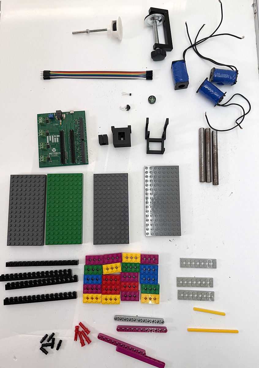
Step 1: Collect the parts
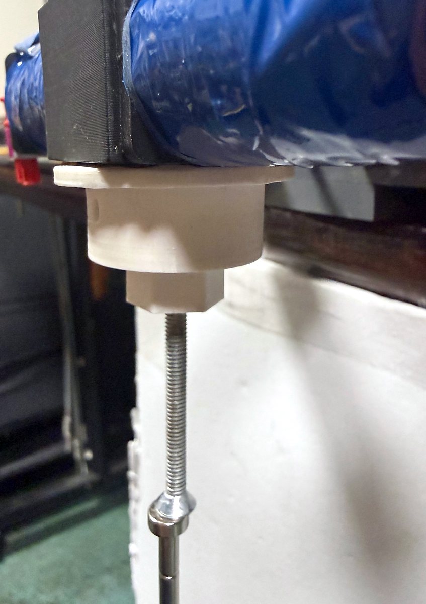
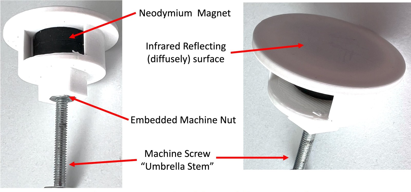
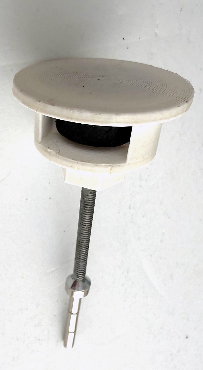
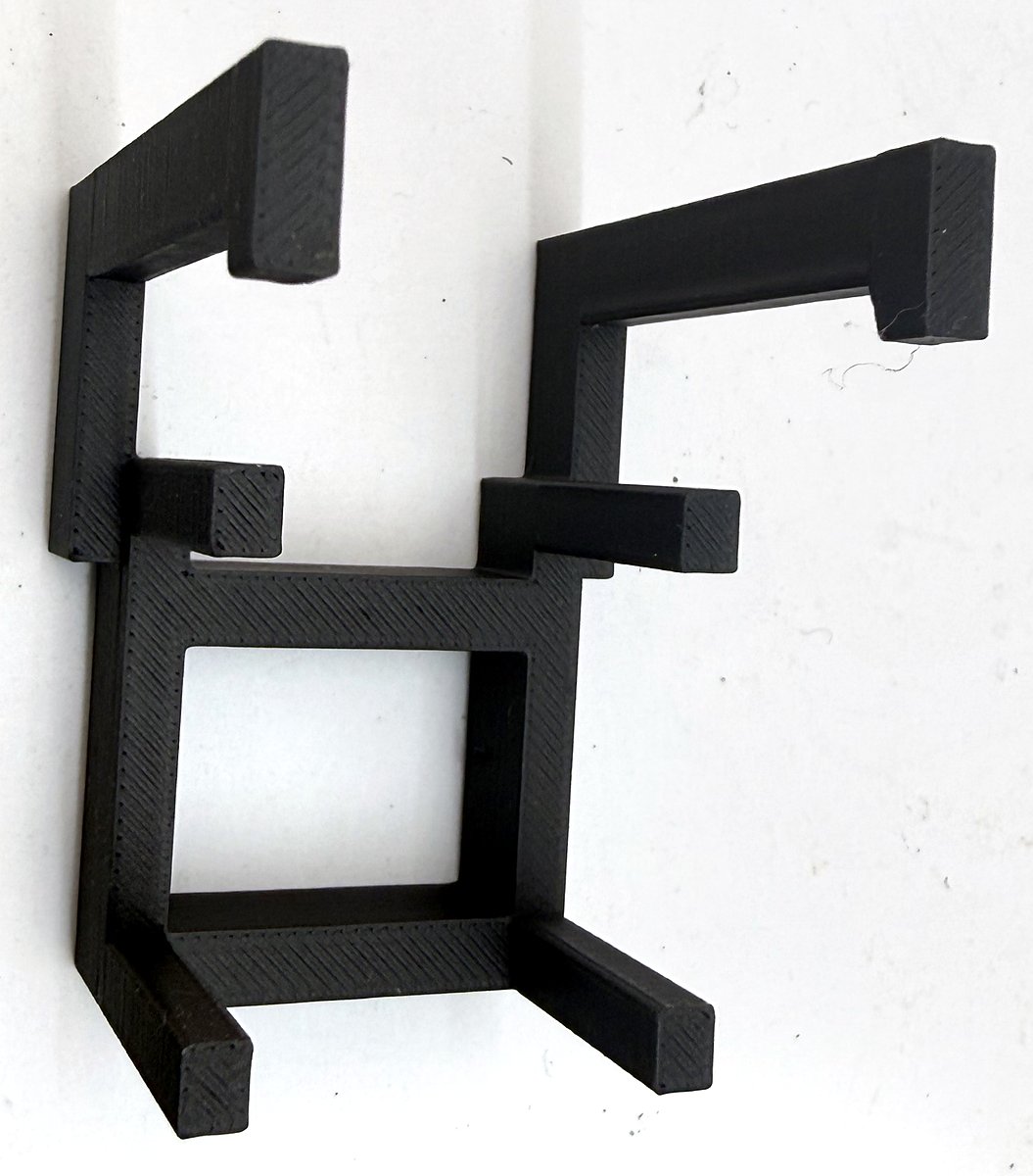
The magnetic umbrella. The umbrella is a 3-D printed holder for a neodymium magnet. Its flat top is a diffuse infrared reflector for the distance sensor, and a flat-head machine screw hangs below it. If the magnet is loose, tighten the screw.
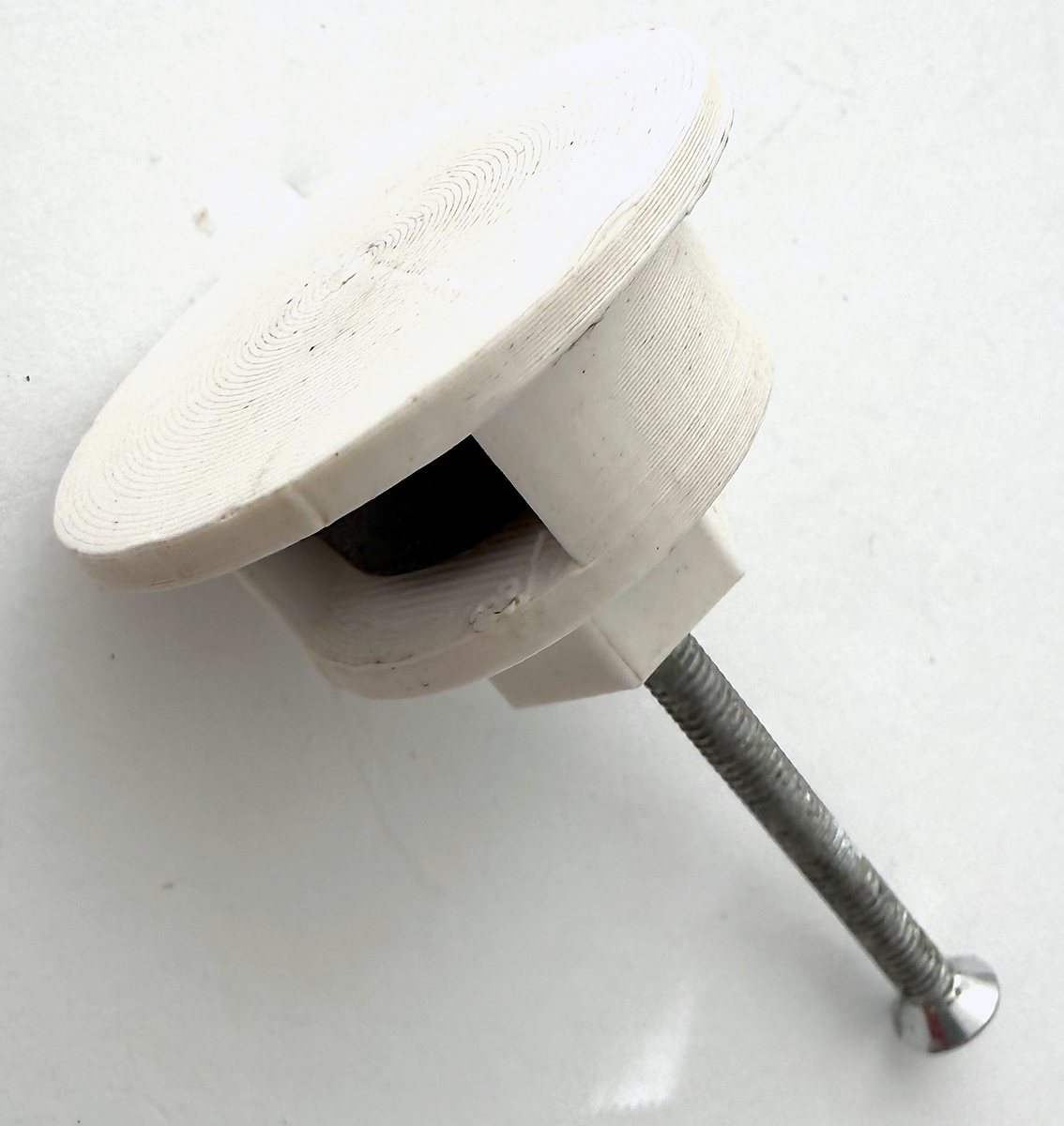
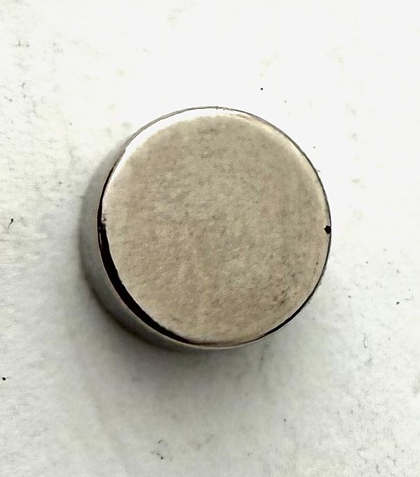
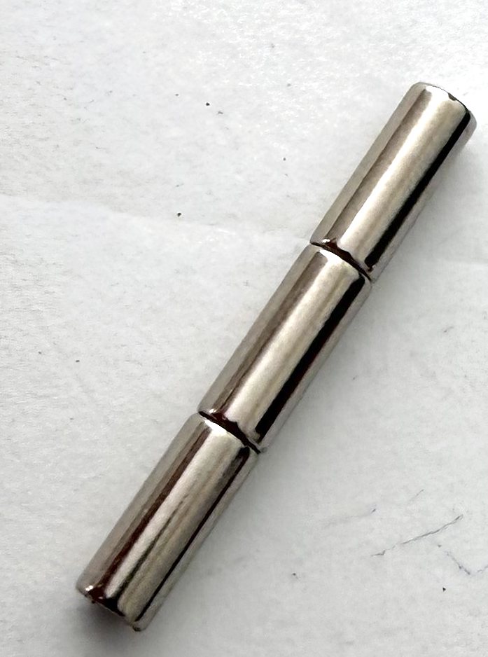
Add the small magnets to the bottom of the umbrella: stick the disc magnet onto the head of the screw, then hang the stack of three small cylinder magnets below the disc.
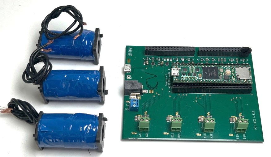
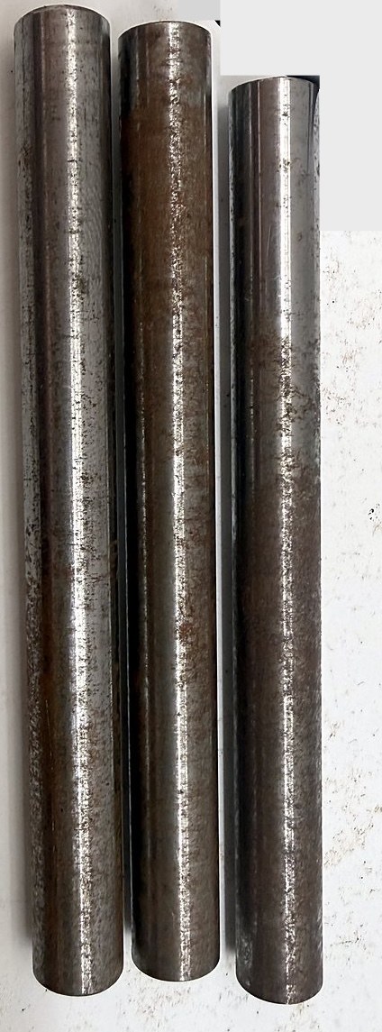
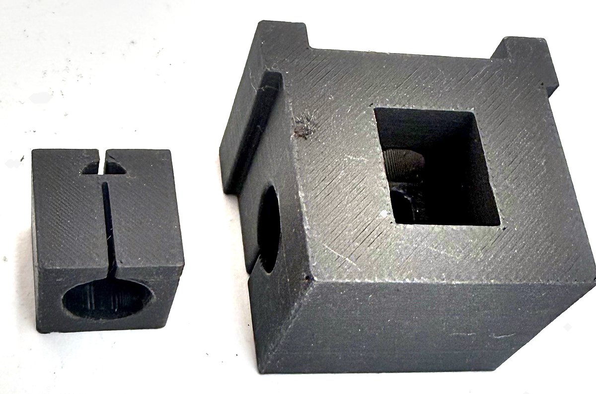
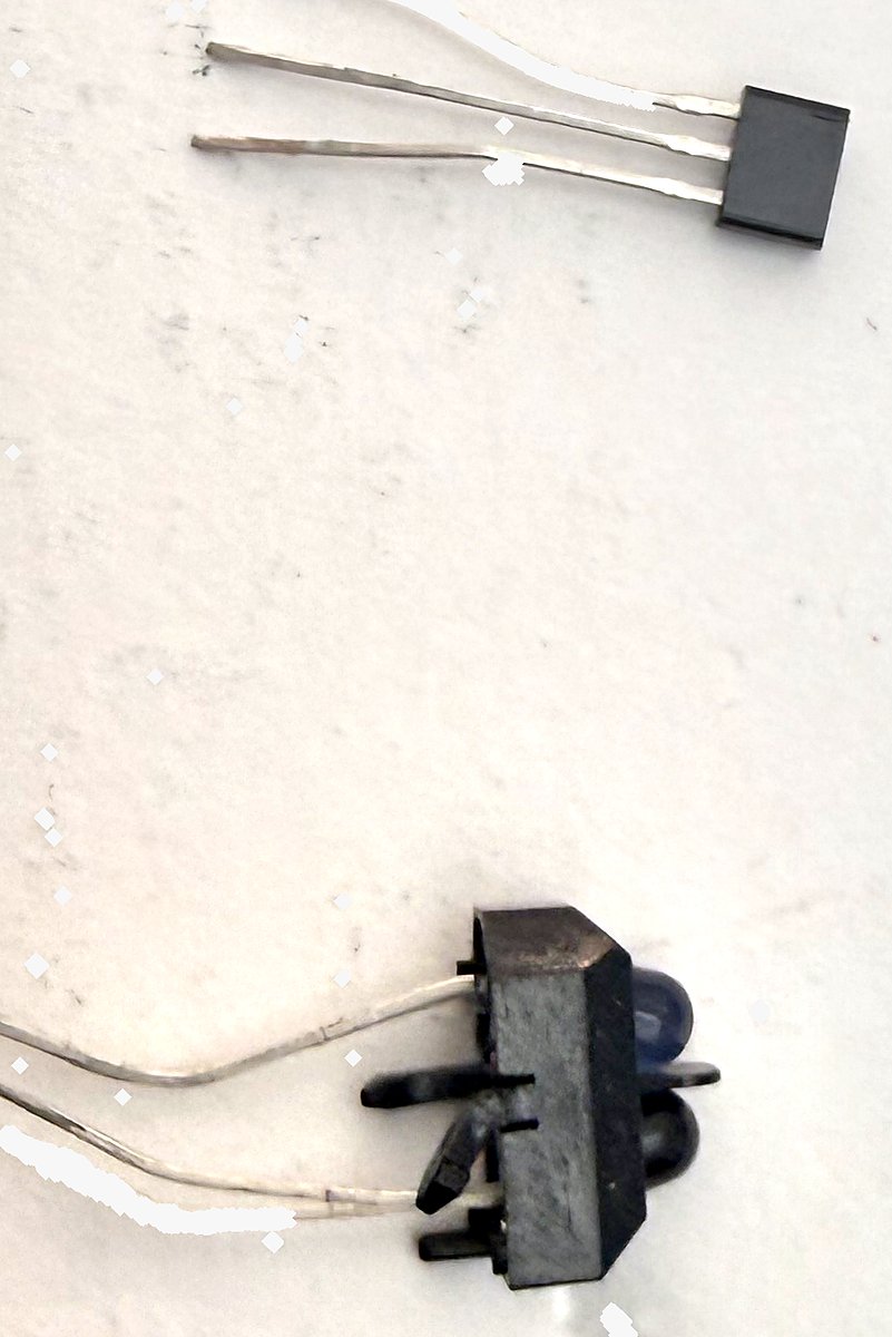

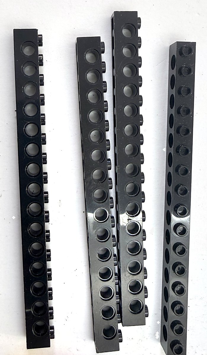
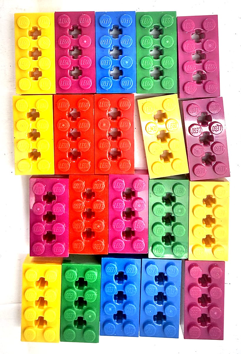
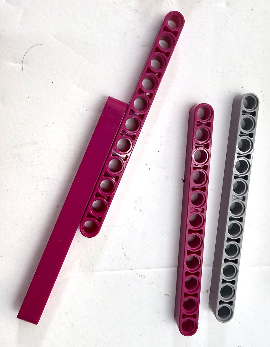
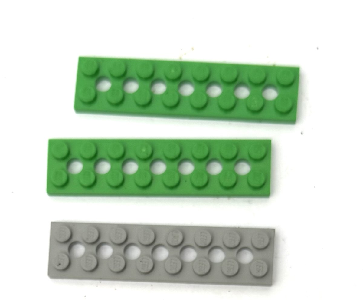
Step 2: Collect the Lego parts
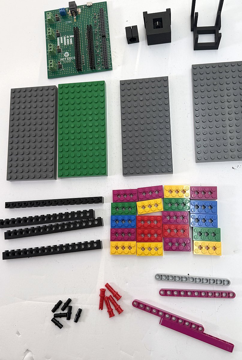
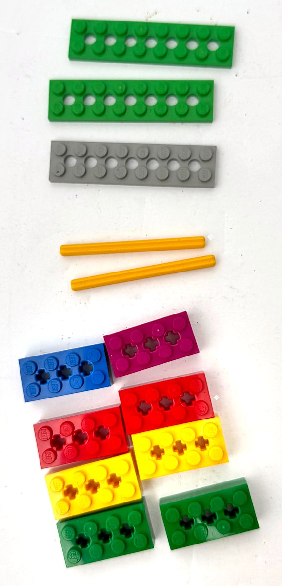
About brick colors: we name the colors of the bricks only so you can find them in our photos. Any color of 2×8 brick works just as well, so use whatever colors you have.
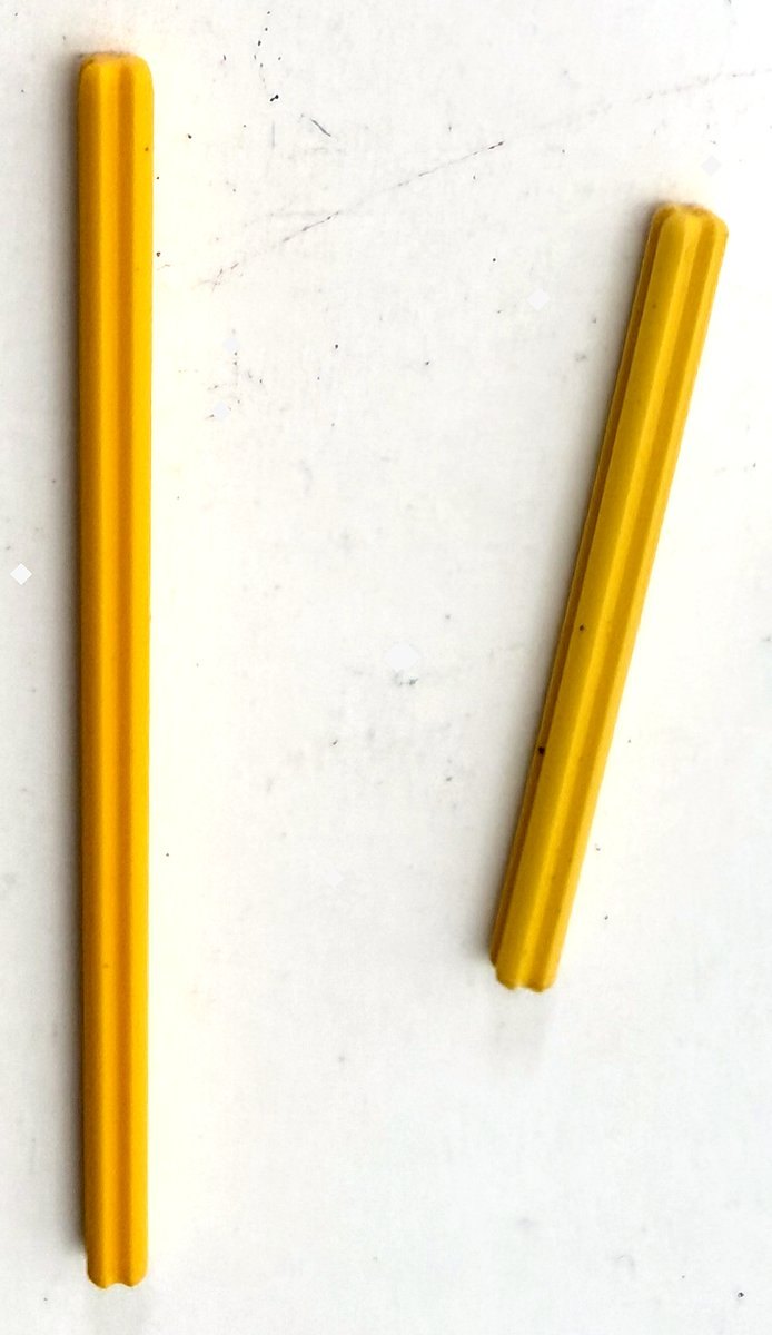
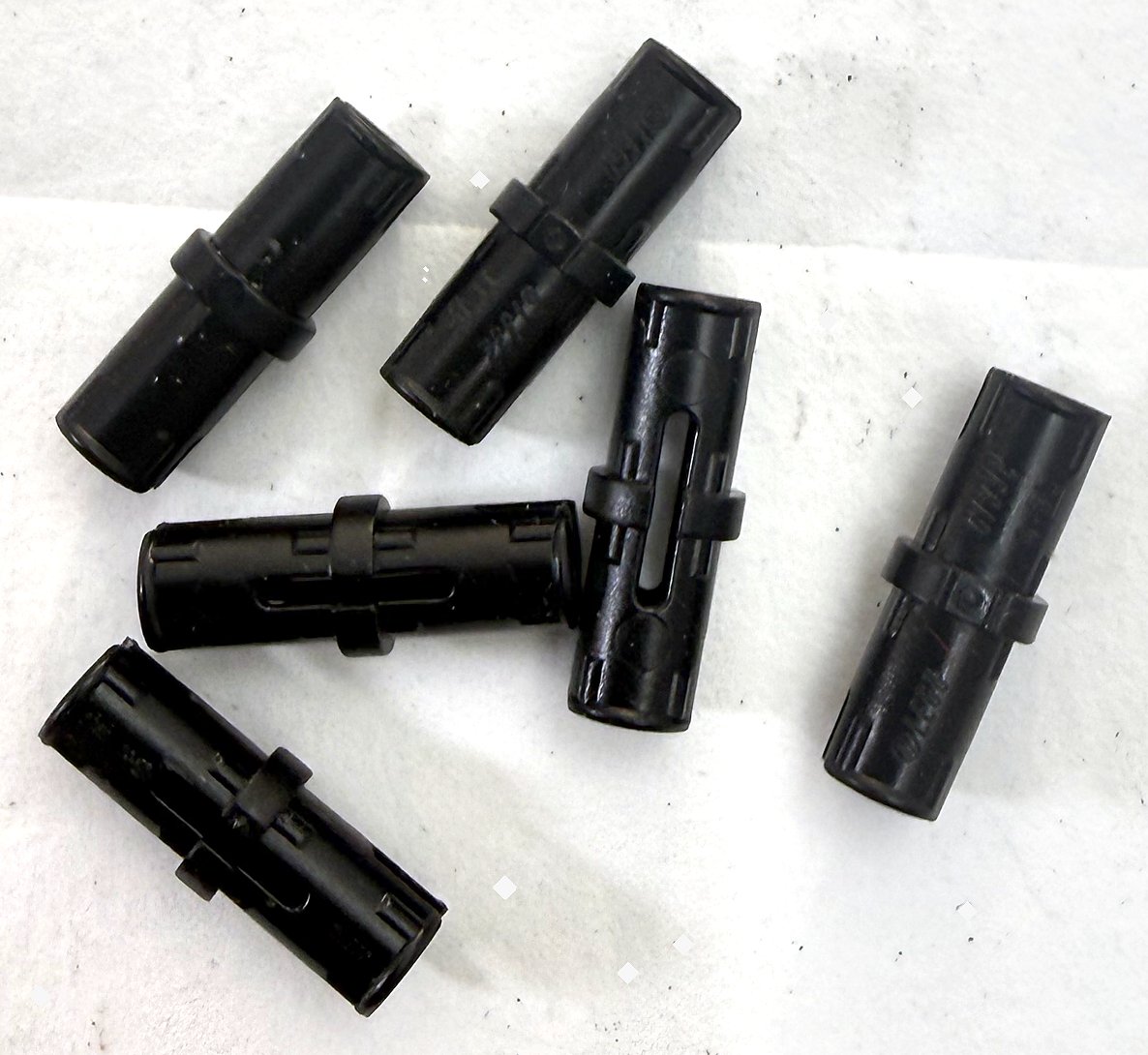
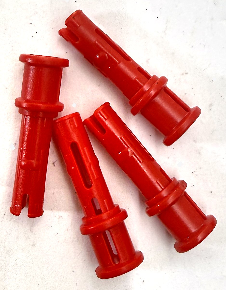
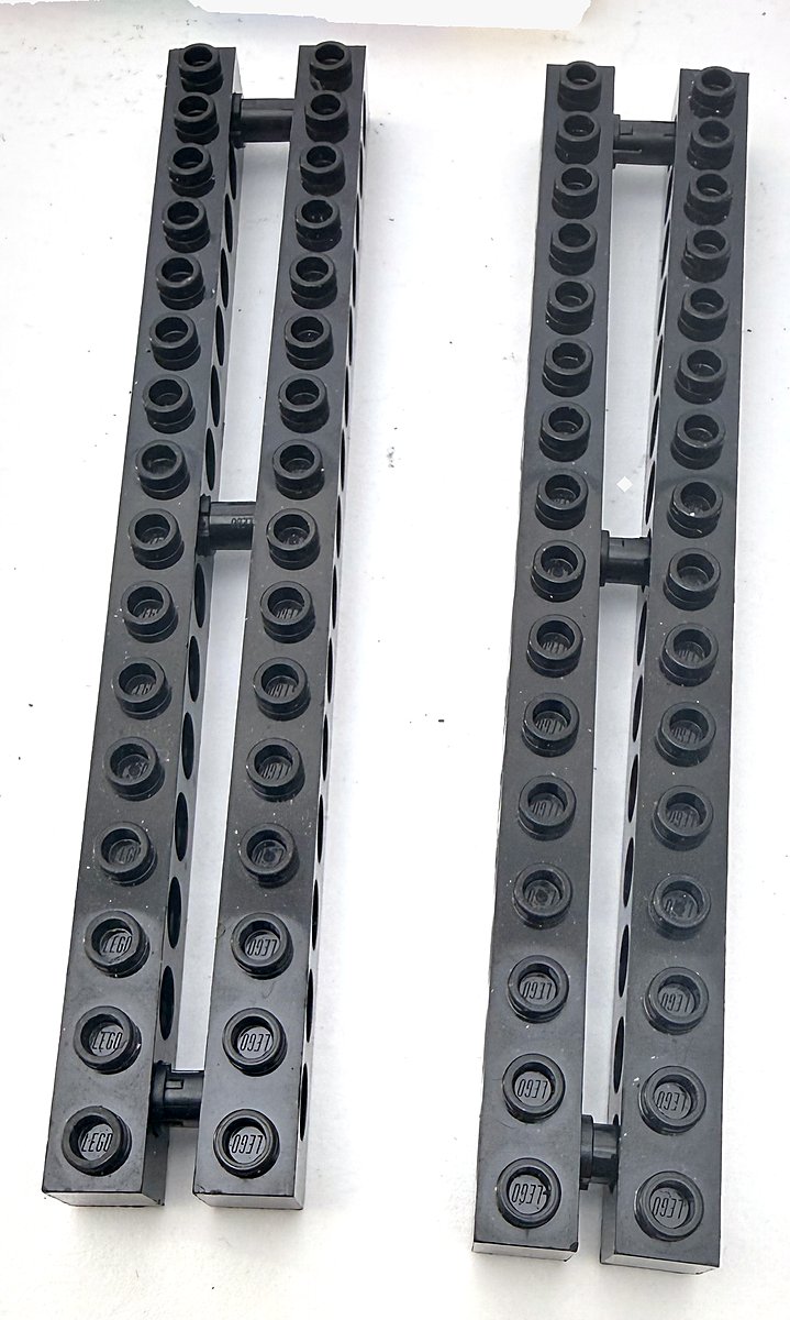
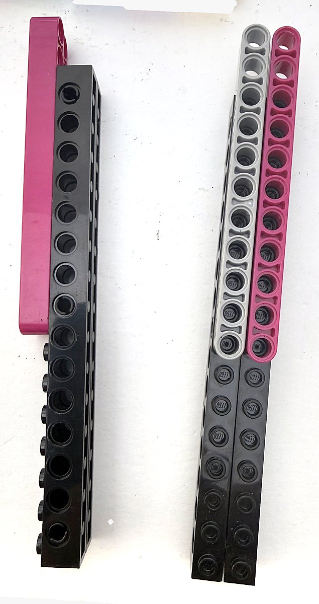
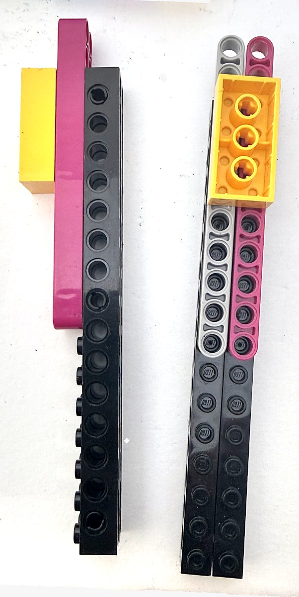
Step 3: Build the two side arms
Pin the long black Technic beams together in pairs, then add the magenta and gray beams and the yellow bricks at the ends.
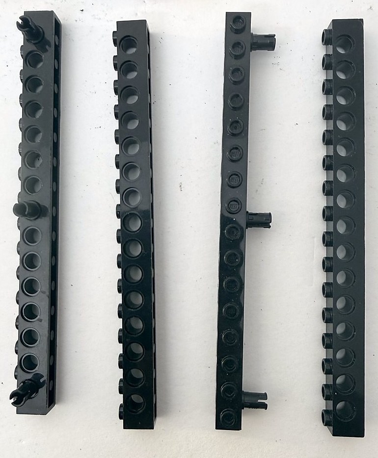
Step 4: Build the base
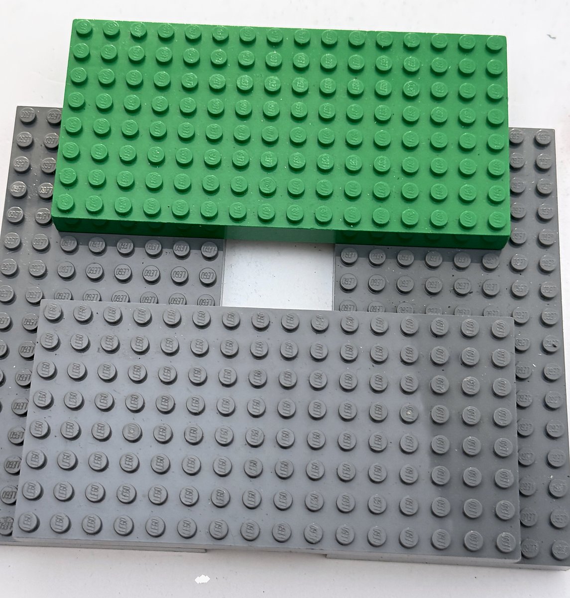
Join the gray plates with the green plate, leaving the square opening shown. Underneath, magenta bricks tie the plates together.
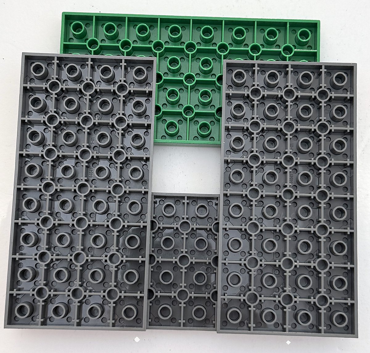
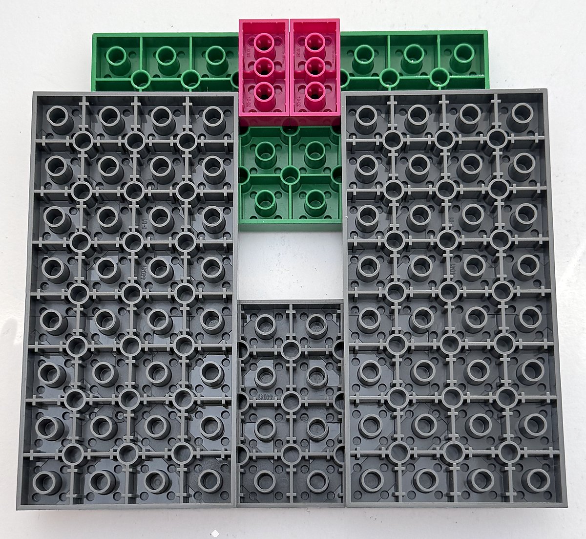
Step 5: Attach the side arms to the base
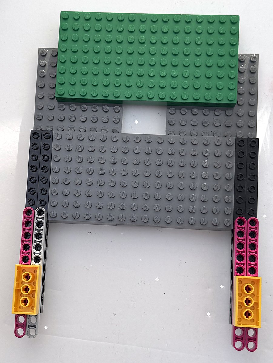
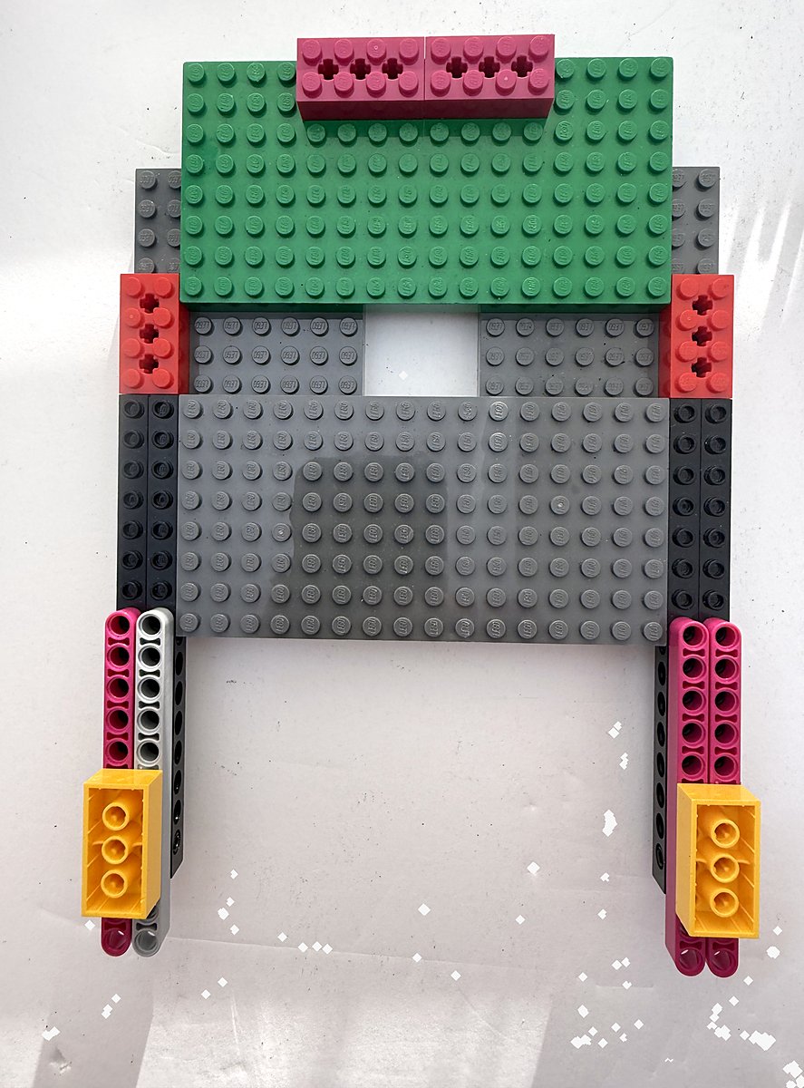
Step 6: Wire the coils and mount the electromagnet and controller board
Prepare each coil wire: twist the stranded copper tightly, then trim the bare end to about ¼". Screw each wire into its driver terminal so that only insulated wire shows outside the terminal. Loose strands outside the terminal can short to the neighboring wire.
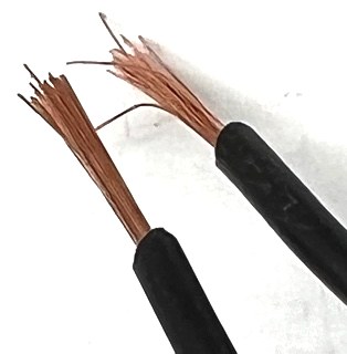
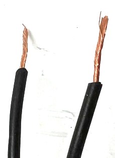
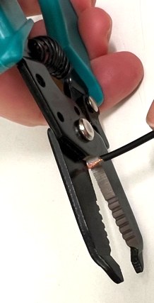
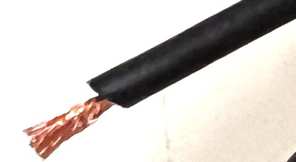
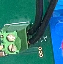
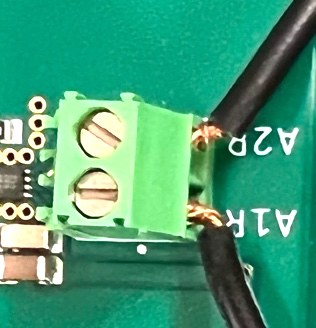
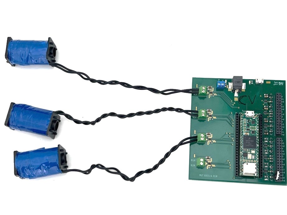
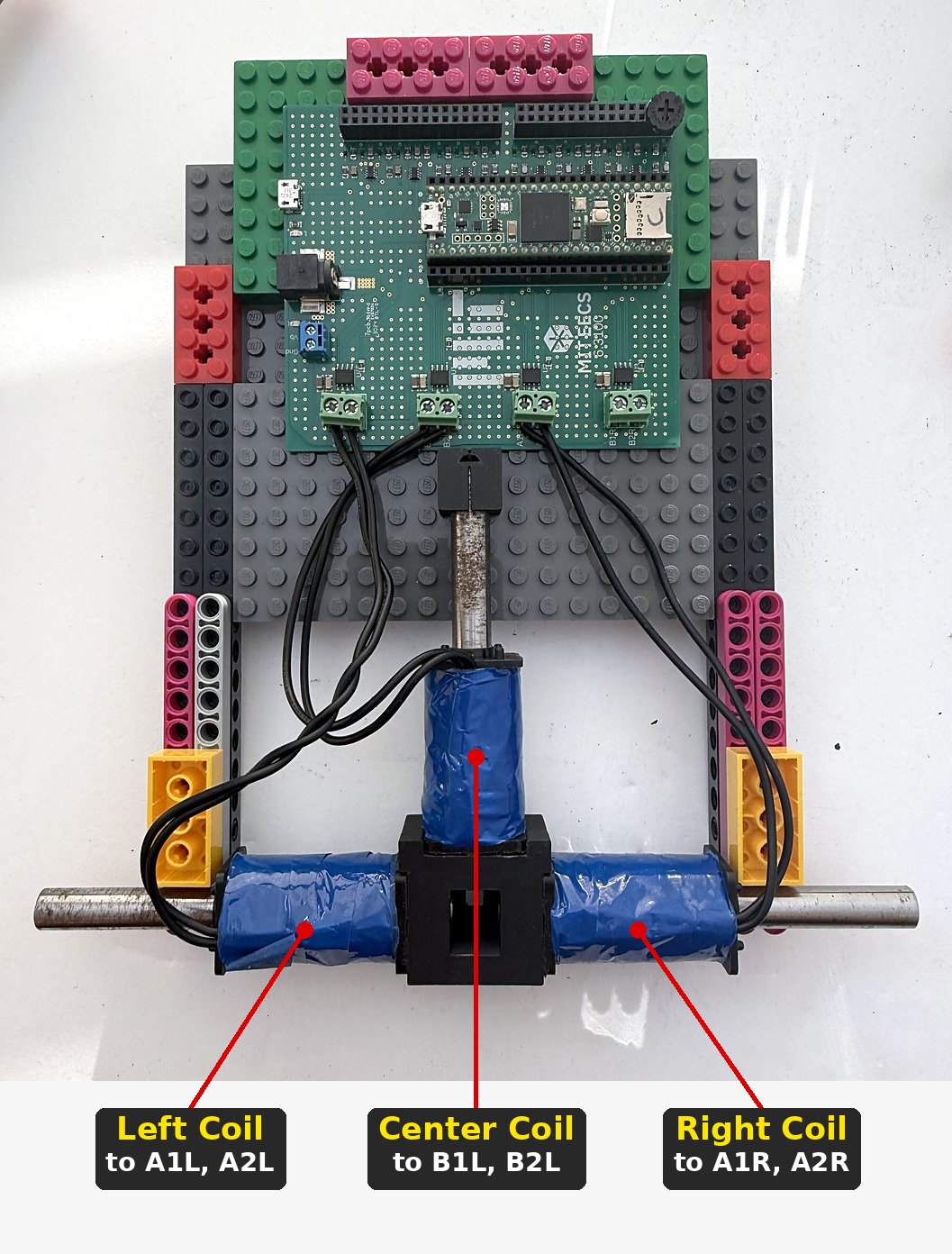
Connect the coils to the driver terminals:
| Coil | Terminals |
|---|---|
| Left | A1L, A2L |
| Center | B1L, B2L |
| Right | A1R, A2R |
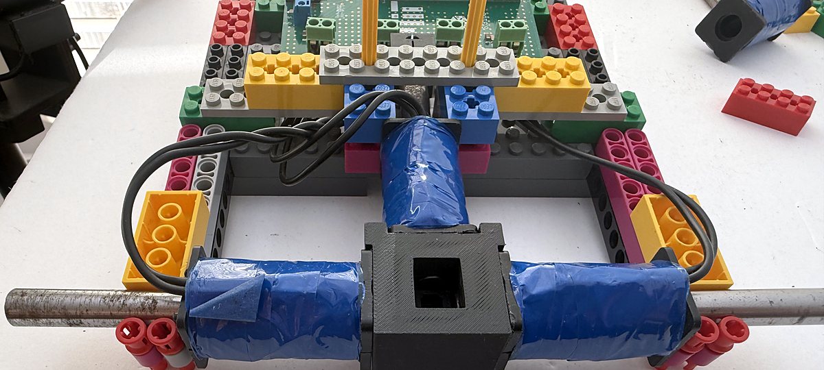
Slide the coils onto the steel rods, with the sensor bracket at the center and the coil wires on top. Then set the electromagnet and the board onto the base.
Step 7: Build and attach the cover bar
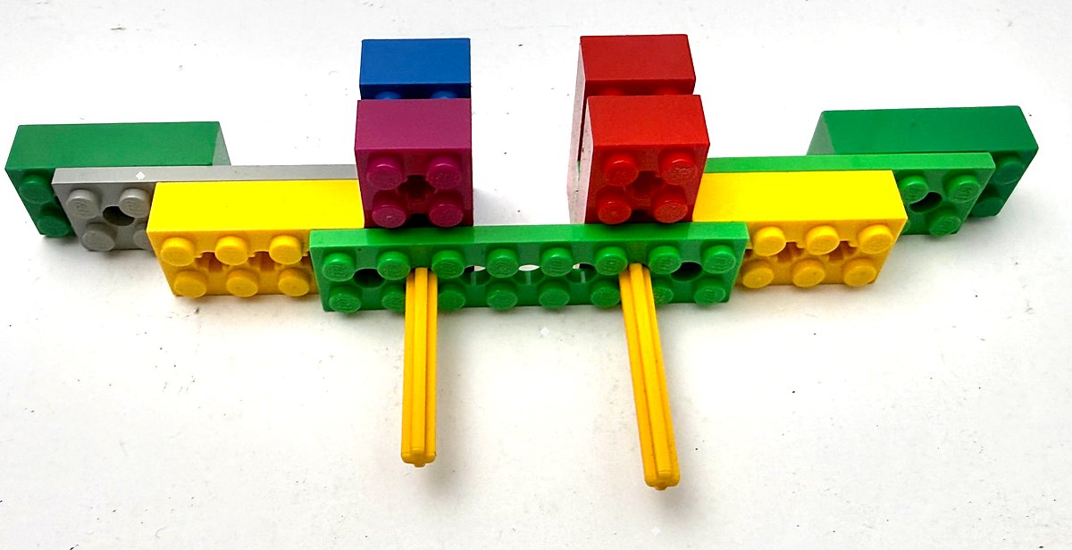
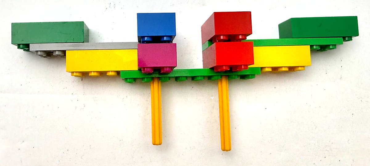
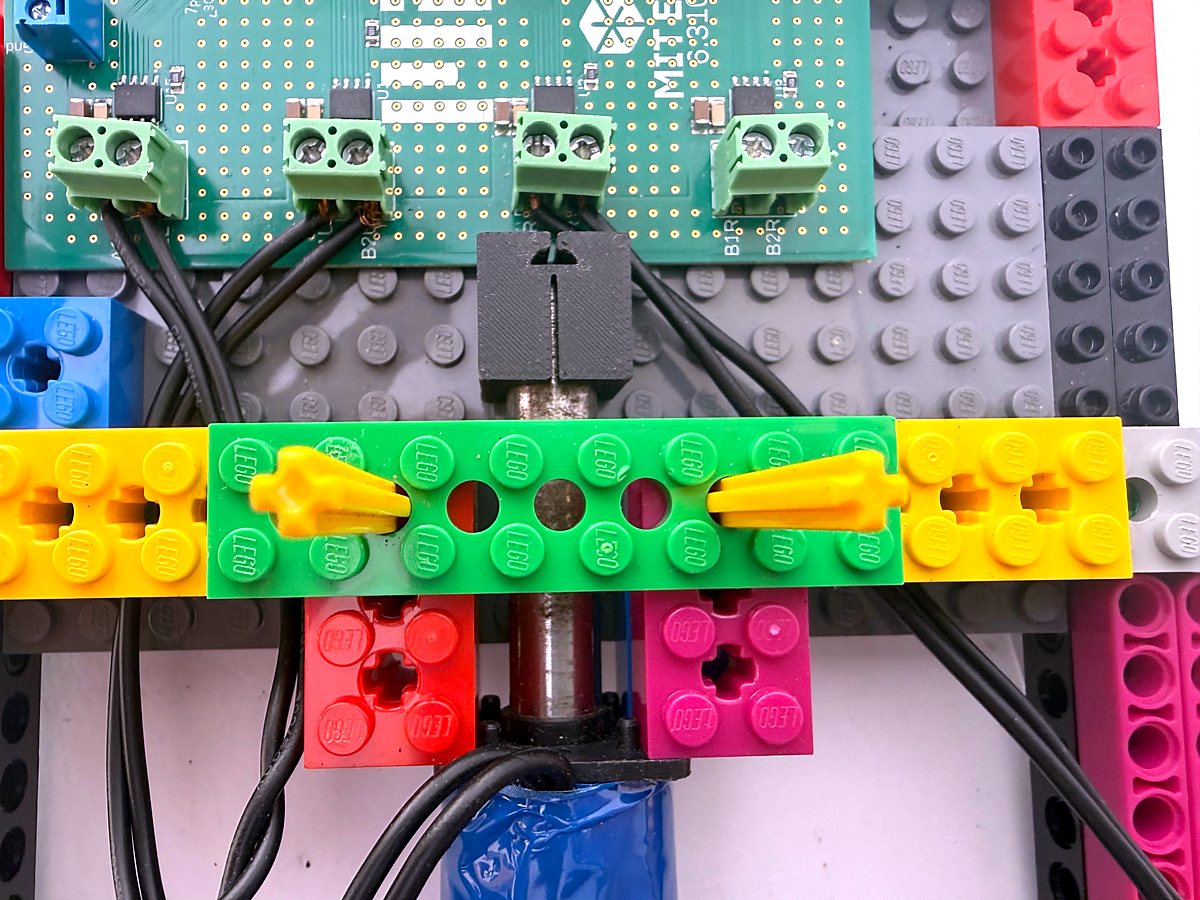
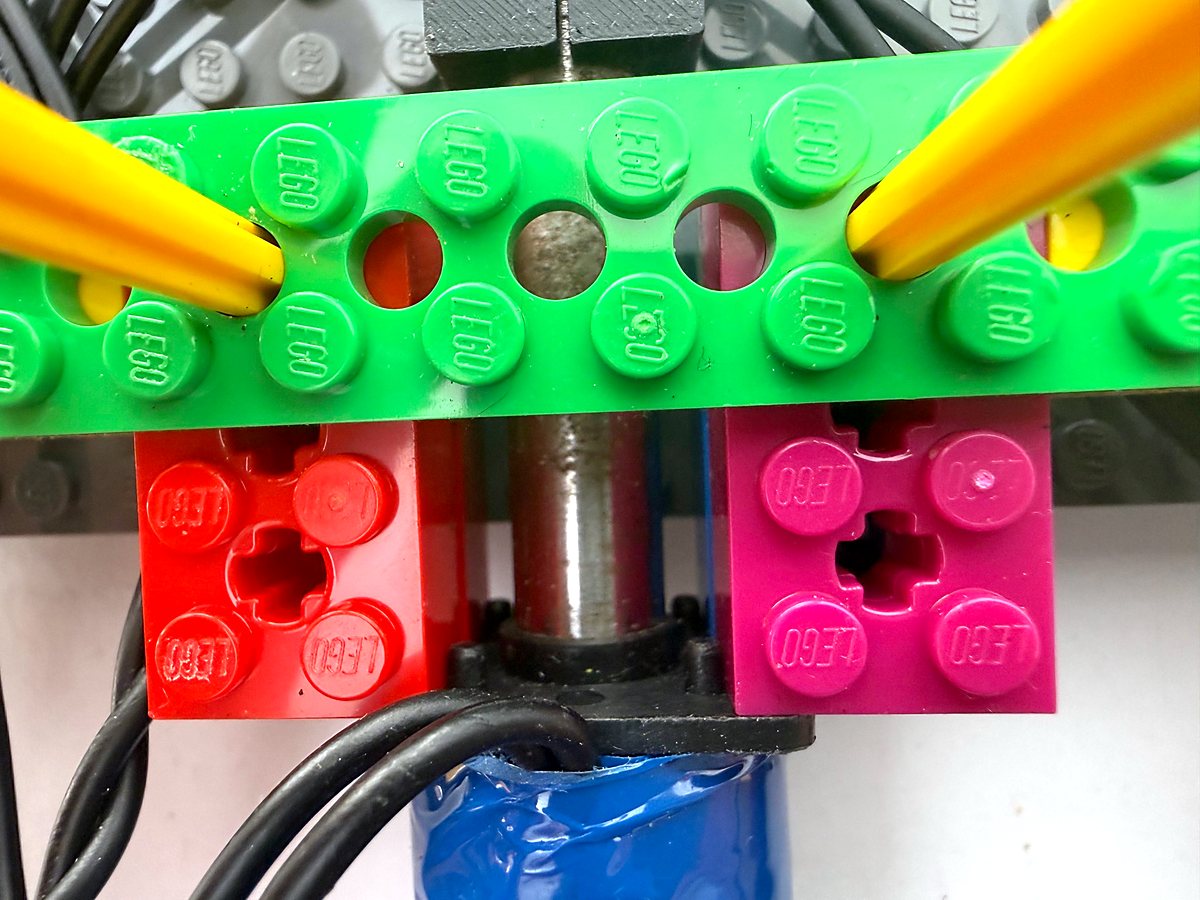
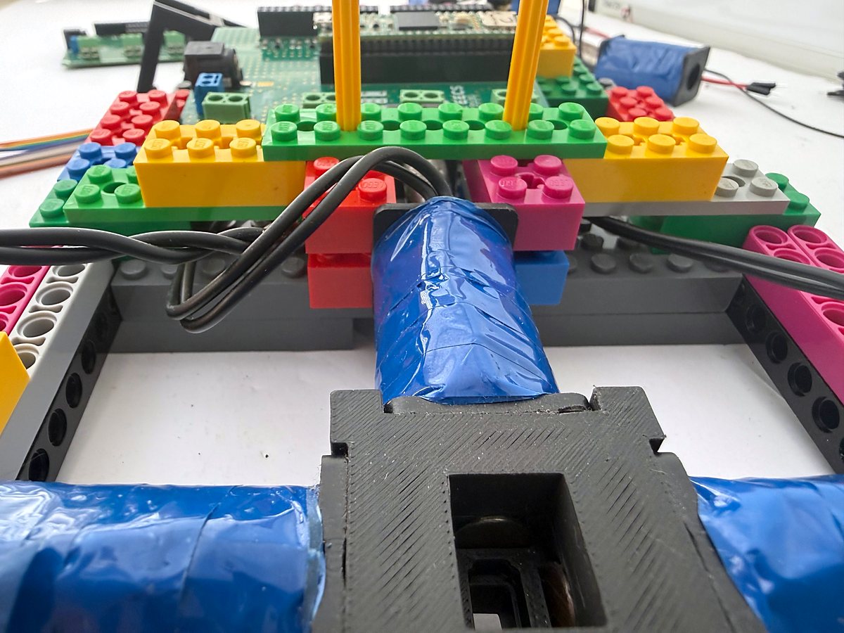
The cover bar holds the center coil in place. Build it from three 2×8 Technic plates (gray or green; either color works), eight 2×4 Technic bricks, and two yellow axles, as shown below. The plates and bricks form a plate-brick-plate-brick sandwich, and the two yellow axles pass through it to stiffen it.
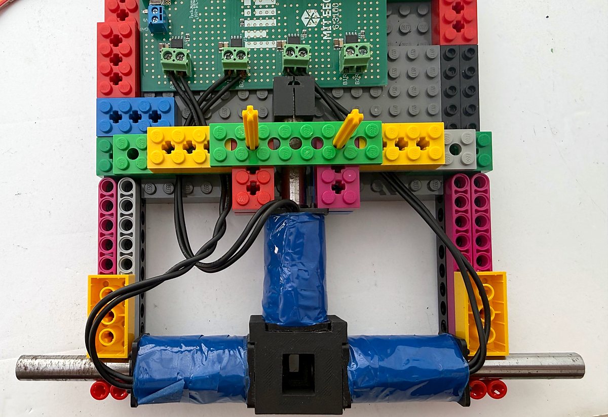
Press the cover bar onto the frame so that the two bricks hanging below it (red and magenta in the photos) push tightly against the black plastic end plate of the center coil, fitting snugly around the studs on that end plate.
Step 8: Lock the outer rods in place
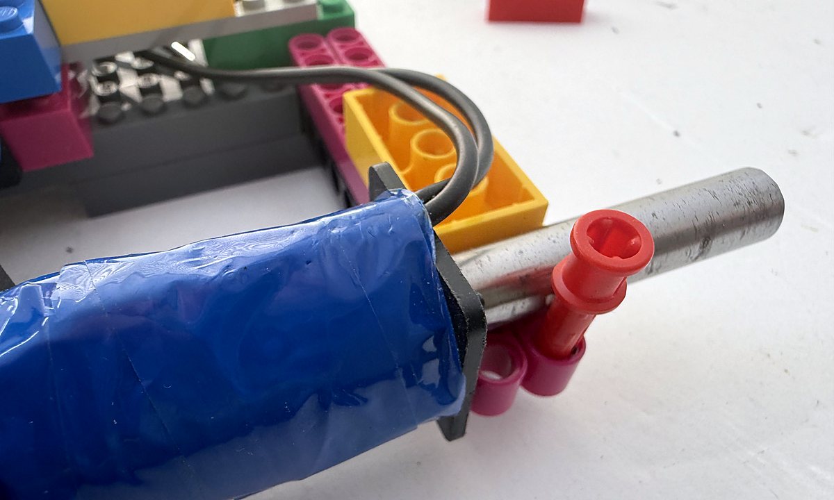
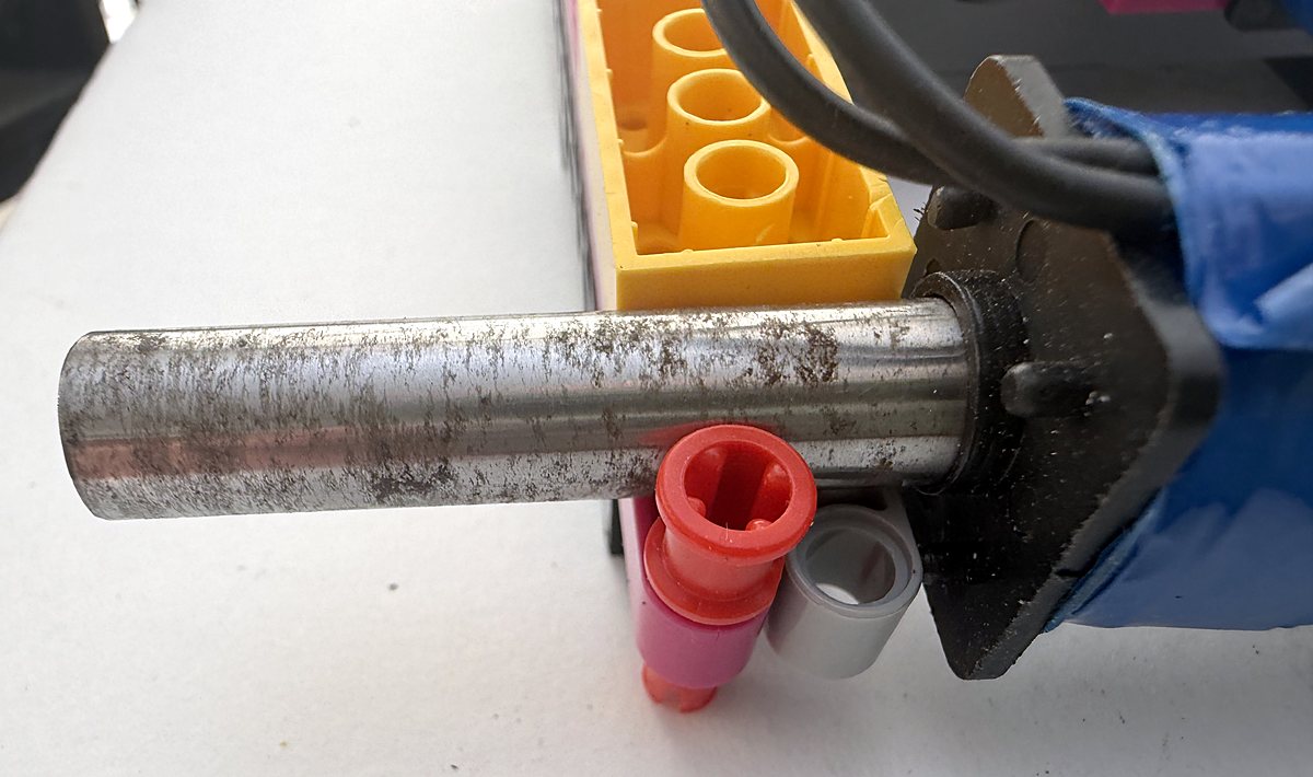
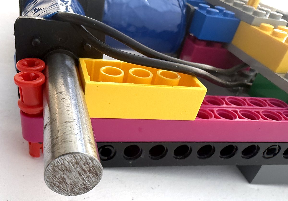
Push red pegs into the arms beside each outer rod, so the rod cannot roll or slide.
Step 9: Make the two sensor cables
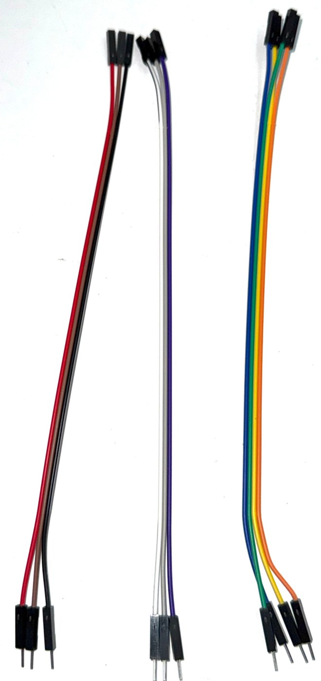
Both sensor cables come from one ten-conductor pin-to-socket cable, with red on the left and orange on the right. Peel it apart from one end to the other into three strips:
- red, brown, black (three conductors) for the magnetic-field sensor;
- white, gray, purple (three conductors), not used in this lab;
- blue, green, yellow, orange (four conductors) for the optical distance sensor.
Step 10: Connect the optical distance sensor
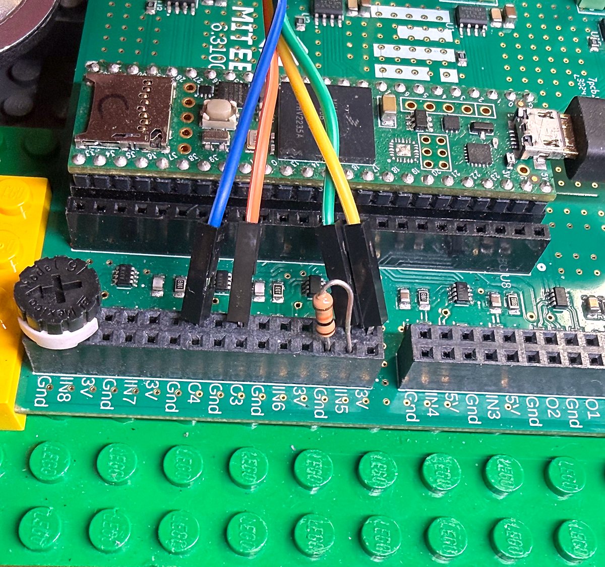
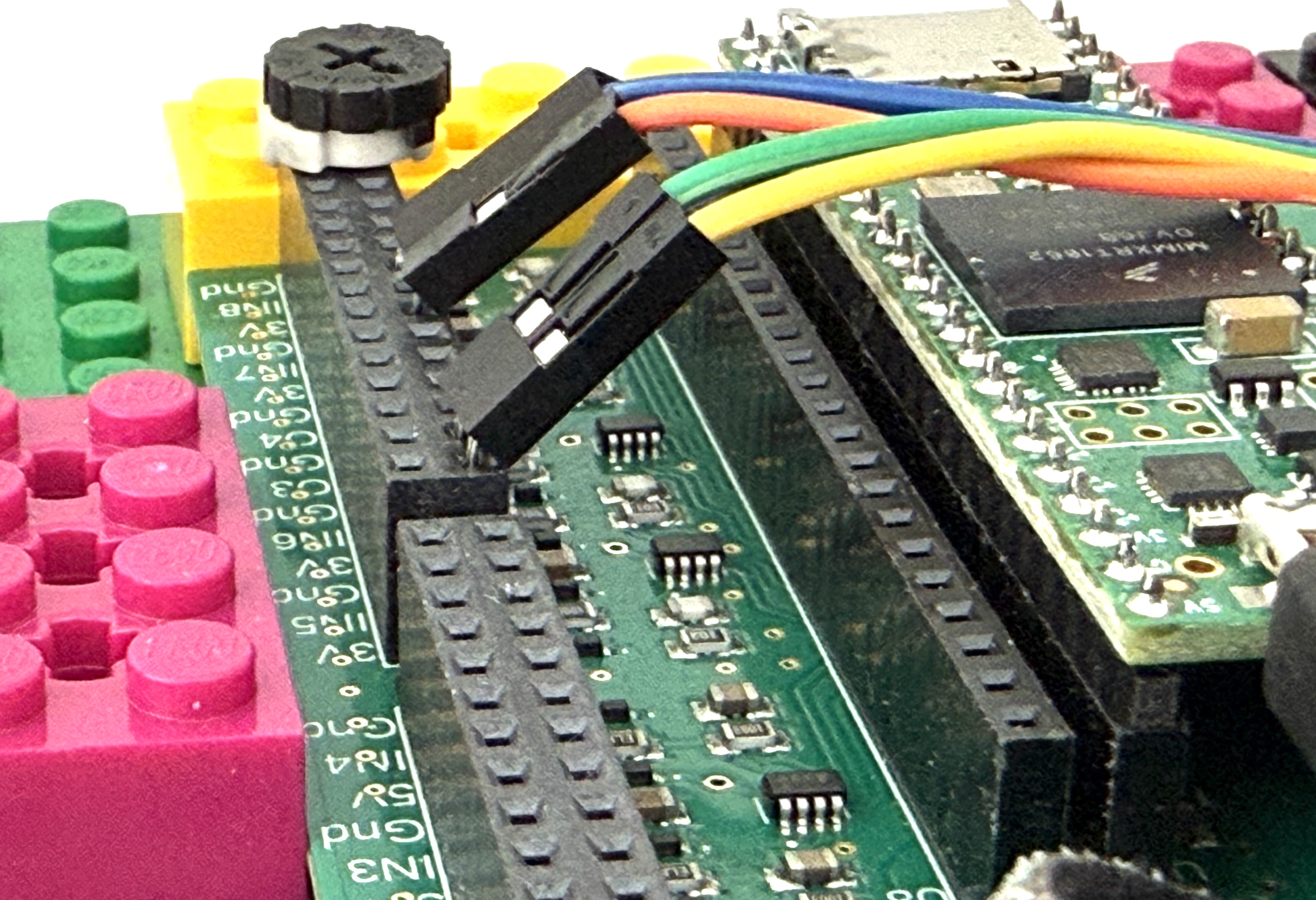
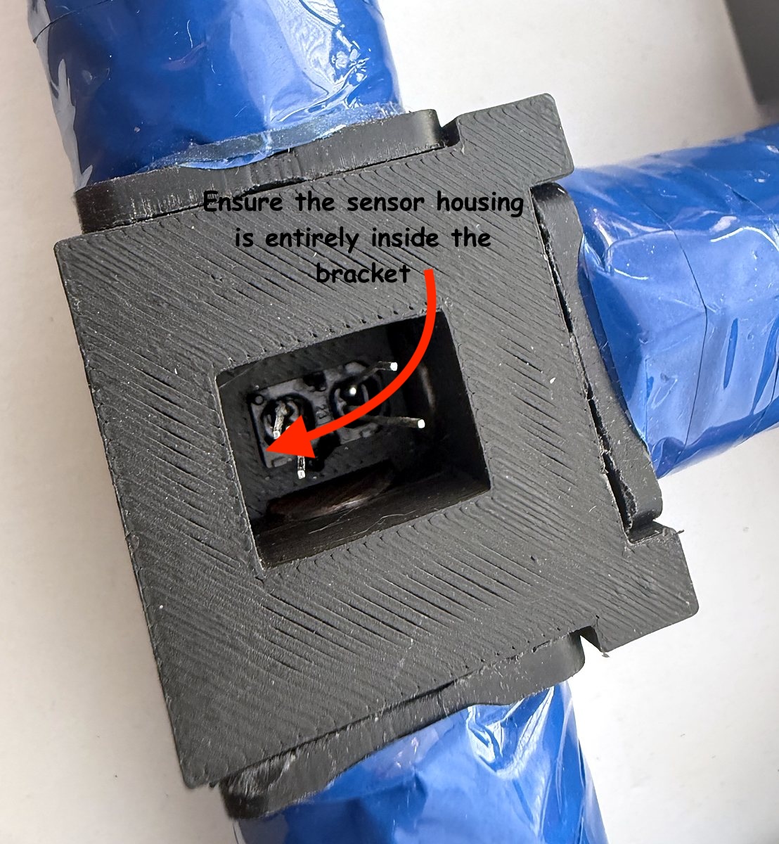
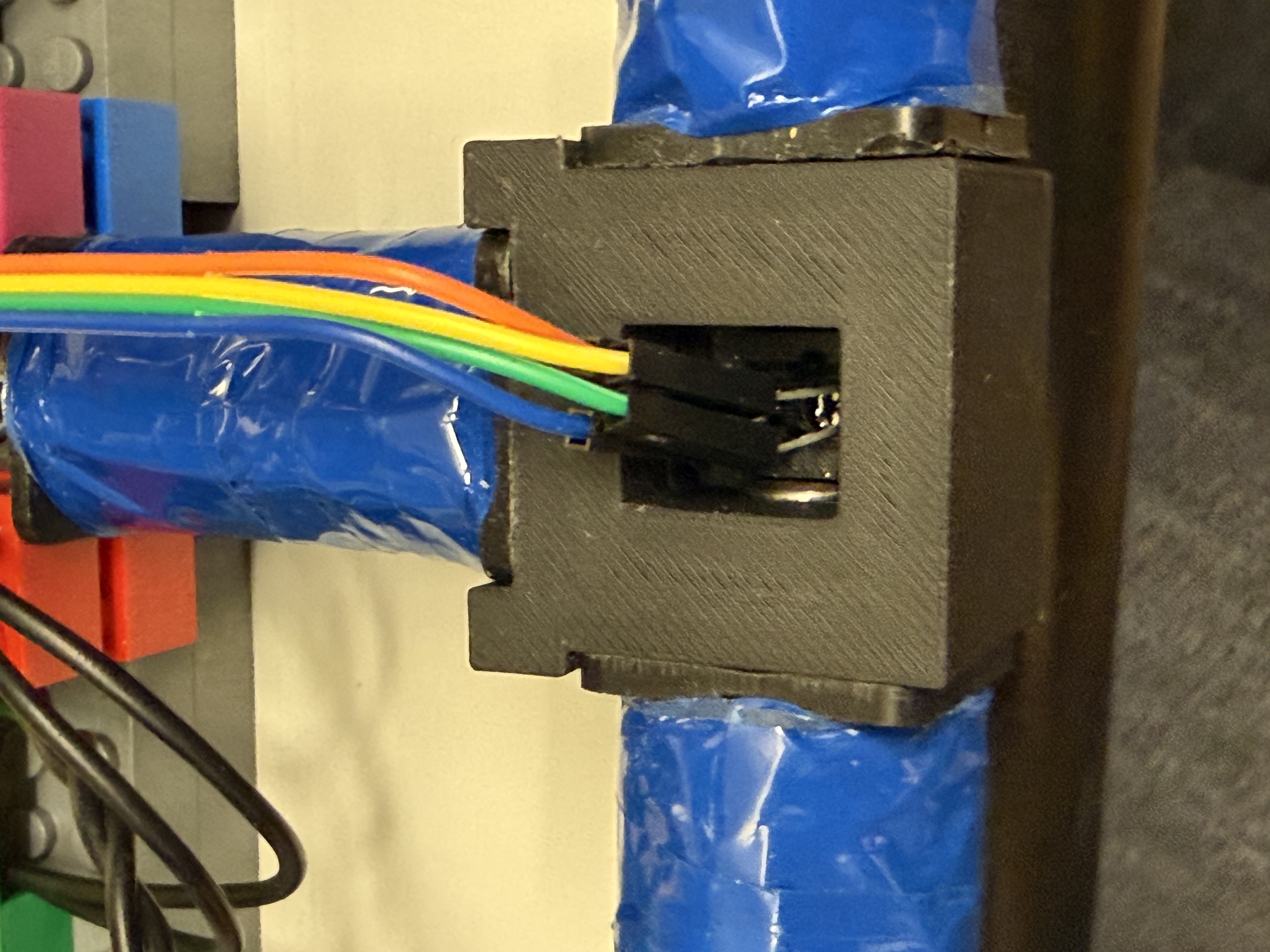
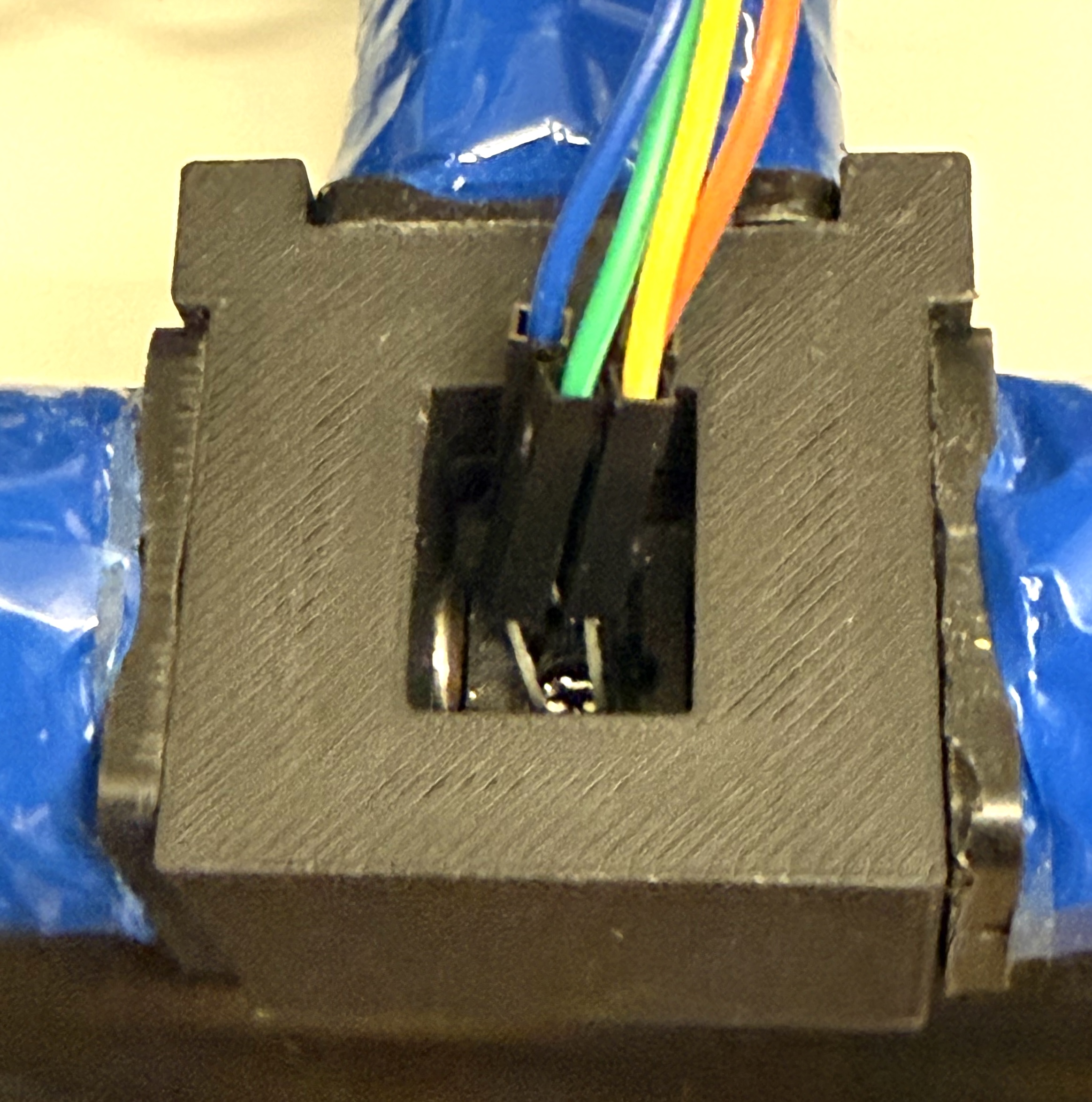
Course staff have already installed the optical sensor in the sensor bracket. Plug the sockets of the blue-green-yellow-orange cable onto the sensor's four leads, and route the cable over the cover bar to the board's header. Keeping it away from the coil wires reduces noise.
| Wire | Board pin |
|---|---|
| Yellow | 3V (not 5V) |
| Green | IN5 |
| Orange | O3 |
| Blue | O4 |
The sensor runs from the 3V supply because the 5V supply is not well regulated, and supply ripple would show up as noise in the distance reading. Also add a 10 kΩ resistor (brown-black-orange) from IN5 to the neighboring Gnd, as shown below. The resistor sets the sensor's output range.


Step 11: Add the magnetic-field sensor
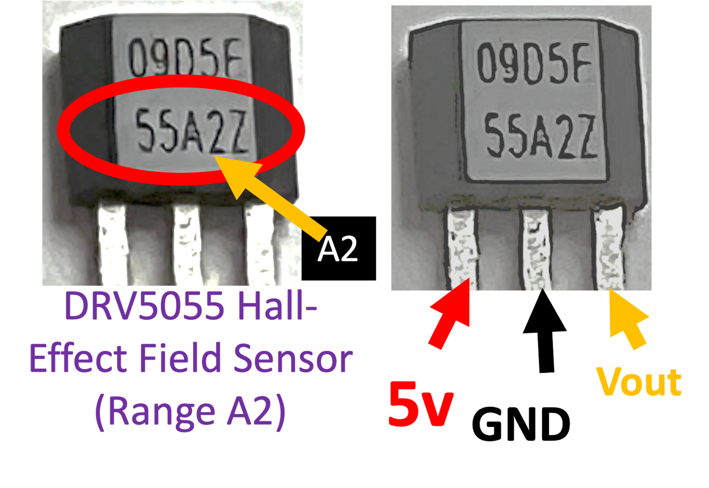
The field sensor is a DRV5055 Hall-effect sensor (range A2, marked "55A2" on its face). Its output voltage is proportional to the magnetic field through it. With the marked face toward you, its leads are 5V, GND and Vout, from left to right.
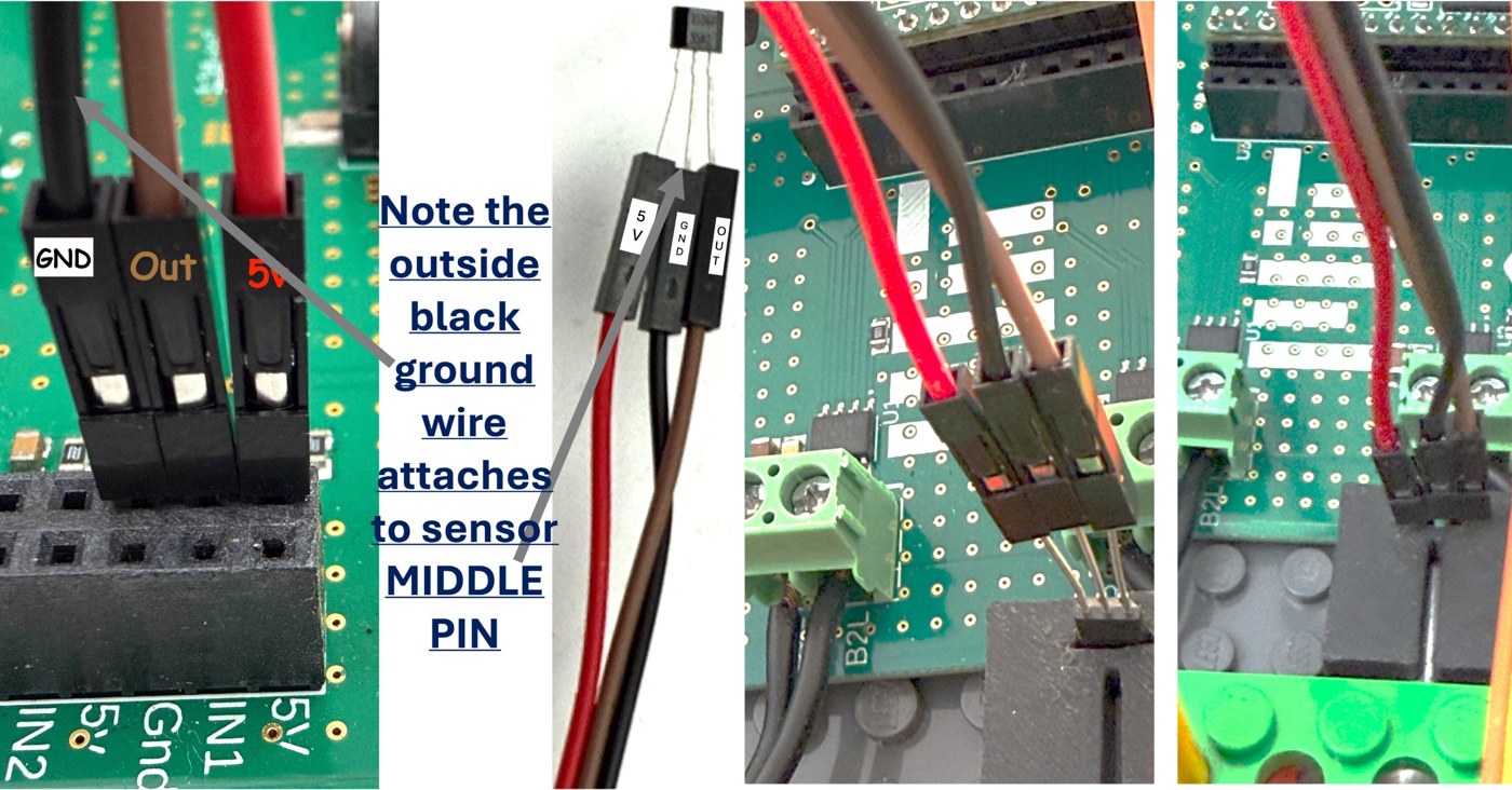
Plug the sensor's leads into the sockets of the red-brown-black cable, push the sensor into its holder, and mount the holder at the end of the center rod. Note that the black (ground) wire, which is on the outside of the strip, goes to the sensor's middle pin. Then plug the cable's pins into the board's header:
| Wire | Sensor lead | Board pin |
|---|---|---|
| Red | 5V | 5V |
| Black | GND (middle pin) | Gnd |
| Brown | Vout | IN1 |
Step 12: Add bricks to hold the board
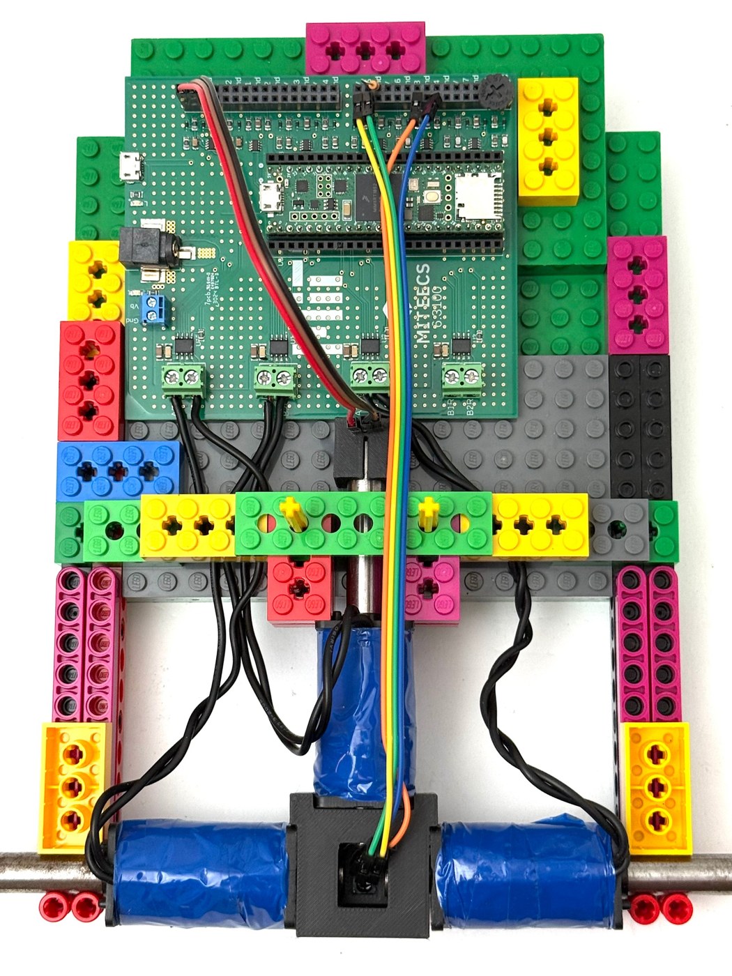
Press a few more bricks onto the base around the controller board, so the board cannot slide: a yellow 2×4 Technic brick at the top right, a yellow brick on the left side above the red bricks, and a magenta brick on the right side, as in the photo.
Step 13: Clamp the maglev to the bench
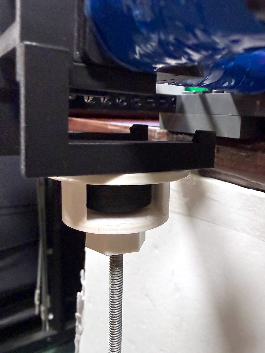
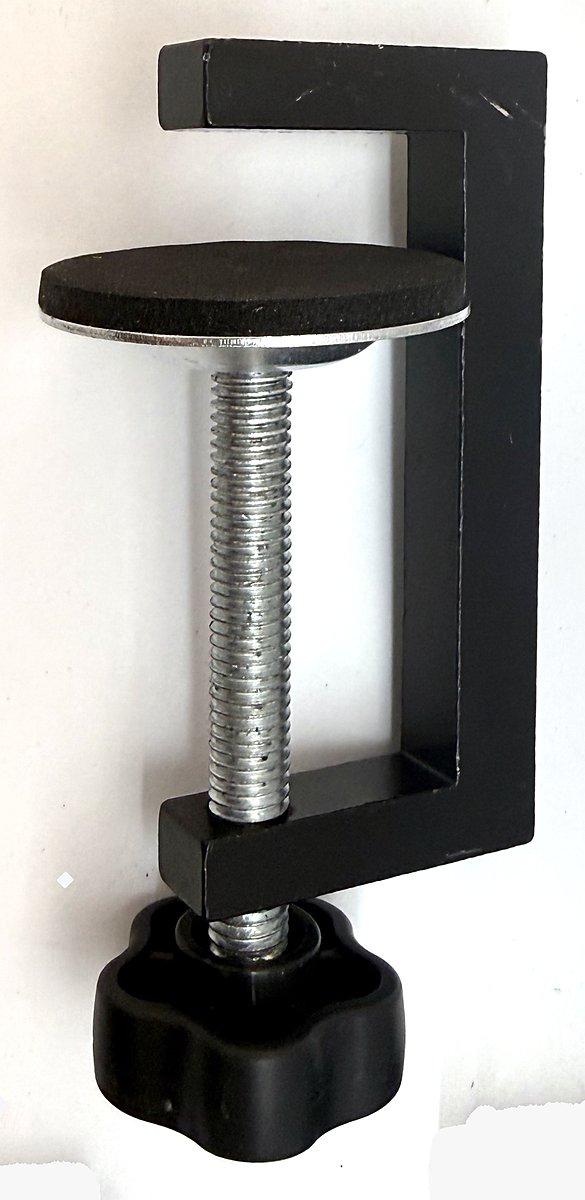
The electromagnet must overhang the bench edge so that the umbrella can hang freely below it.
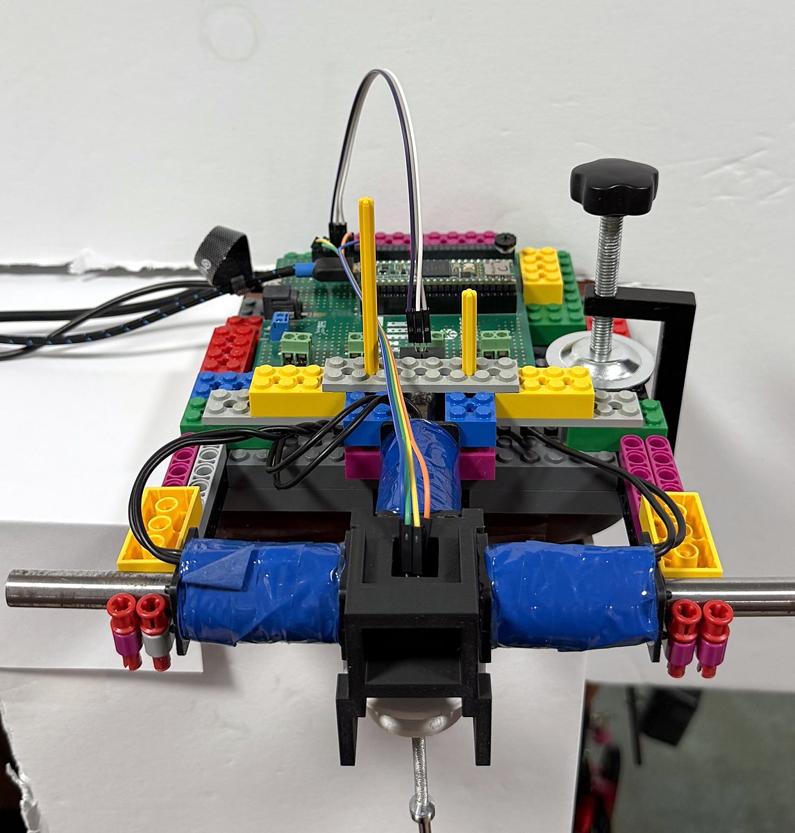
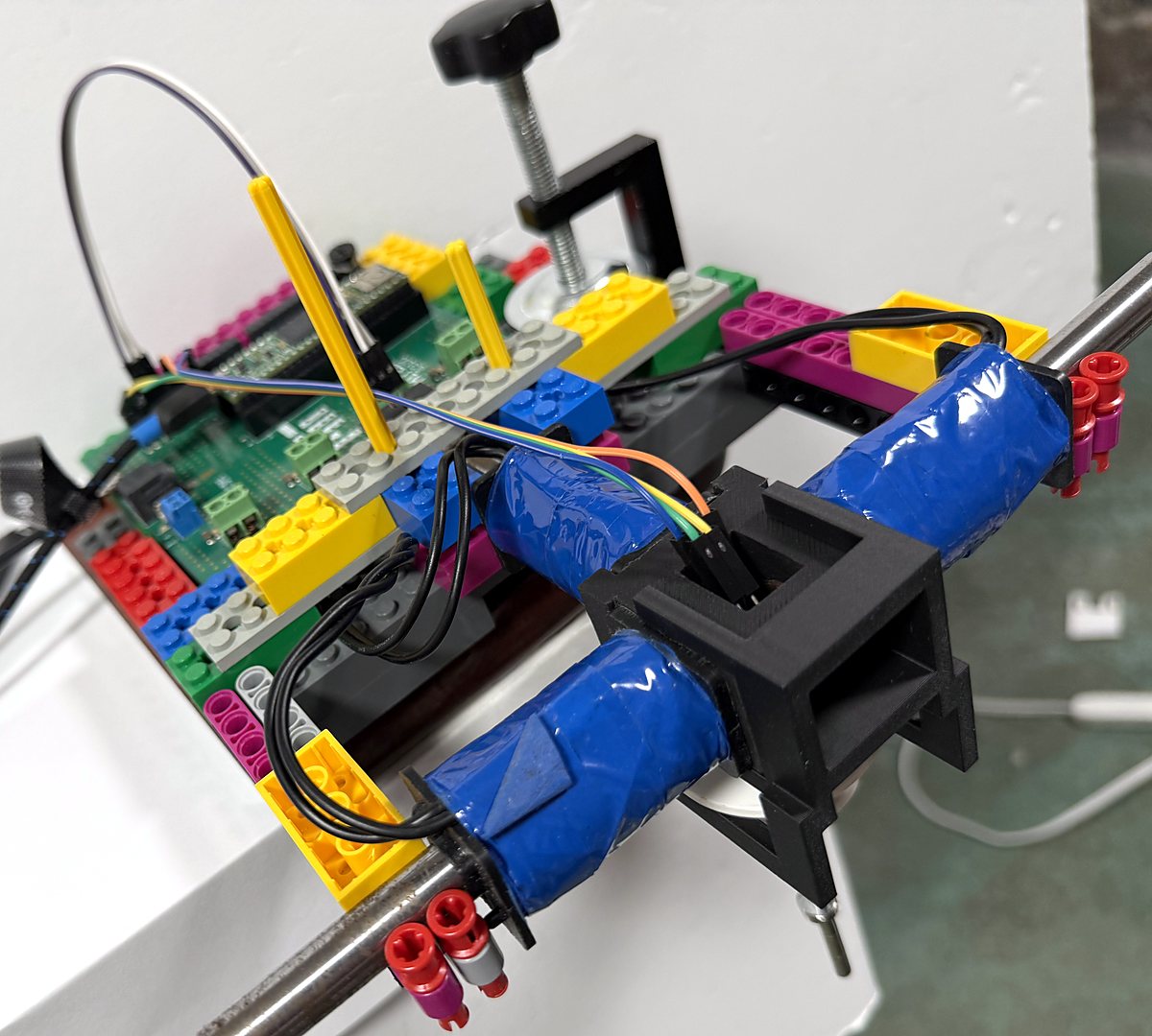
Checking the Coil Directions
All three coils must produce fields in the same direction. If one is reversed, it fights the other two, and the umbrella will not float.
- Connect your laptop and both 5V supplies (USB and driver) to the board; both power lights should be on.
- Set
MODEto 0 on line 11, upload the sketch, and open the serial plotter. - Send a slow square wave:
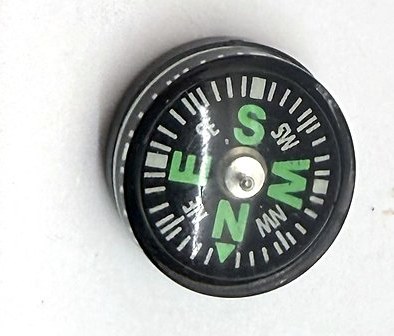
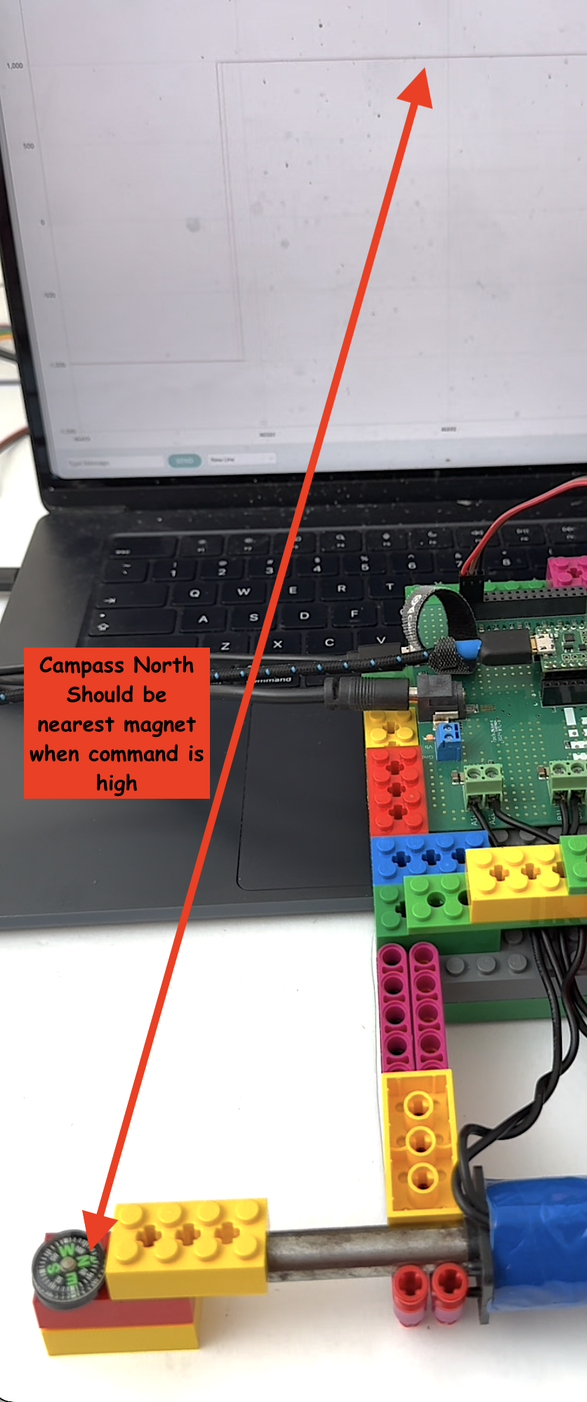
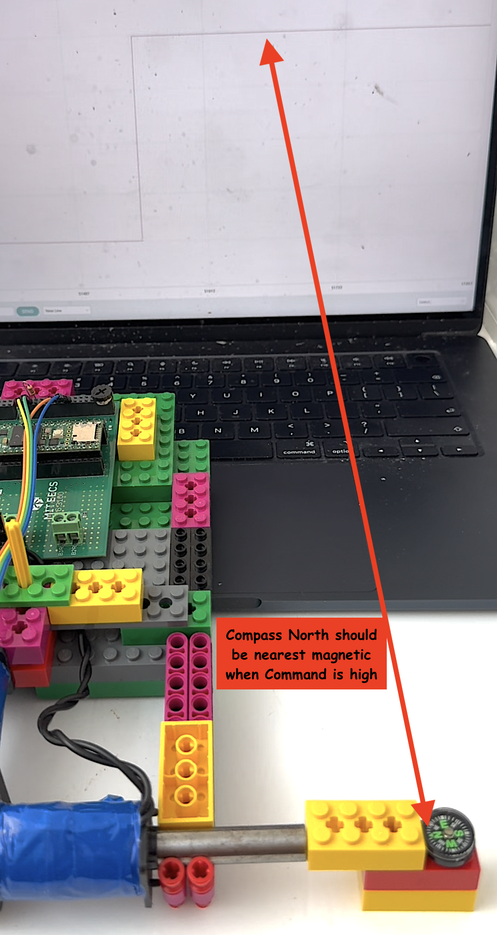
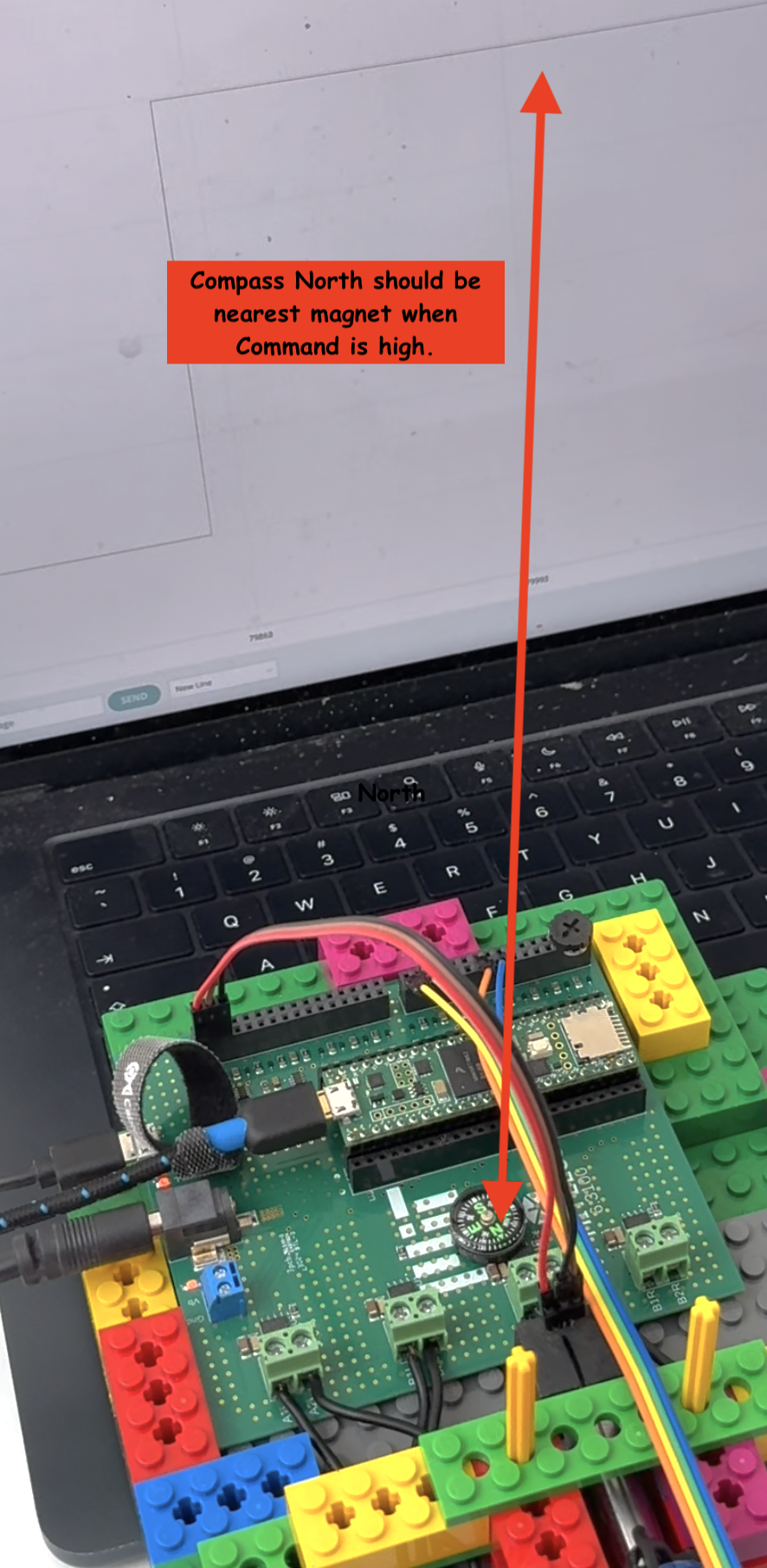
6 1(amplitude 1),5 0.1(0.1 Hz, so the command flips every 5 seconds) and4 100(slows the plot to match). Plot only Cmd. - Set the compass on a brick, one brick-width from the end of each steel rod in turn, as in the videos below. The needle should swing back and forth as the command flips.
- For every coil, the needle should point north when Cmd is high.
Use the same compass for all three coils. These compasses are easily remagnetized, so two compasses may not agree with each other.
If a coil's needle points south when Cmd is high, reverse that coil's command in the sketch: swap the last two arguments of its hbridgeBipolar call, upload again, and recheck.
208  cmdCL = my6310.hbridgeBipolar(coilCmd, B1L,B2L); // center: B2L <-> B1L swaps direction
209  my6310.hbridgeBipolar(coilCmd, A2L,A1L);         // left:   A1L <-> A2L swaps direction
210  my6310.hbridgeBipolar(coilCmd, A2R,A1R);         // right:  A1R <-> A2R swaps direction
After making needed swaps, retest the coils with the compass, they should behave like the examples below.
Matching the Field Sensor to the Command
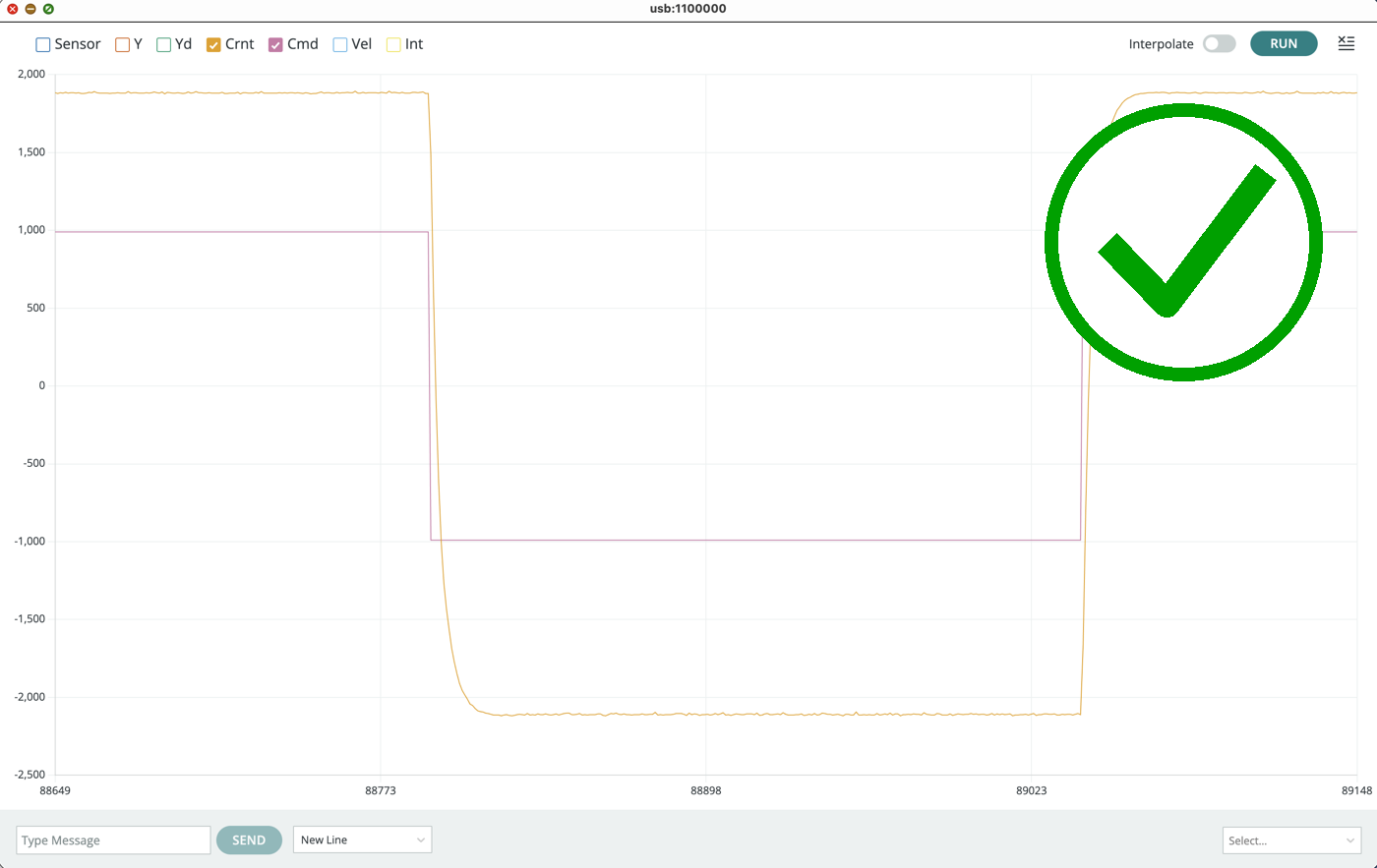
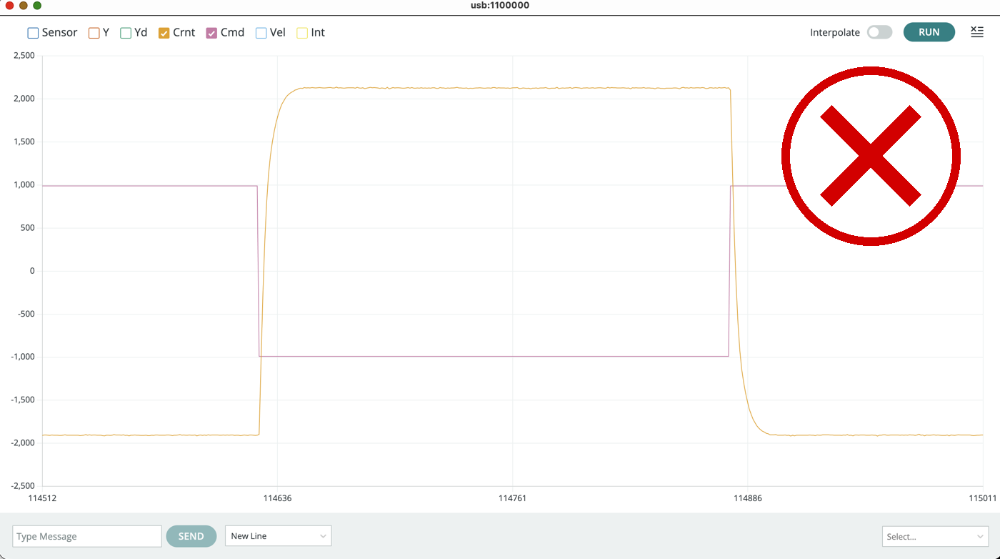
Once all three coils agree, check that the field sensor's reading (Crnt) has the same sign as the coil command (Cmd). Later labs model the path from command to field, and a sign flip here would make that model wrong.
- Keep
MODEat 0, with the sketch uploaded and the serial plotter open. - Send
6 1(square-wave amplitude 1) and5 1(1 Hz). - Turn off every trace except Cmd and Crnt.
- Check that Crnt steps up when Cmd steps up, and down when Cmd steps down.
If Crnt moves opposite to Cmd, flip the sign of crntSign on line 15 of the sketch (-1.0 to 1.0, or the reverse), upload again, and recheck.
If you later reverse the coil commands to fix the feedback sign (in the lab, when you first try feedback), you will need to flip crntSign again.
crntSignTesting the Distance Sensor's Range
Check the distance sensor's reading at the two extremes of the umbrella's travel. (You will calibrate the sensor in the lab.)
- Keep
MODEat 0, send6 0(amplitude zero), and plot only Sensor, the raw sensor reading x (between 0 and 1). In MODE 0 with zero amplitude, the potentiometer sets a steady coil command. - Turn the potentiometer so that the electromagnet pulls the umbrella up. Leave it there for the rest of the range test.
- +15 mm: let the electromagnet pull the umbrella up against the sensor-and-rod bracket, and note the reading.
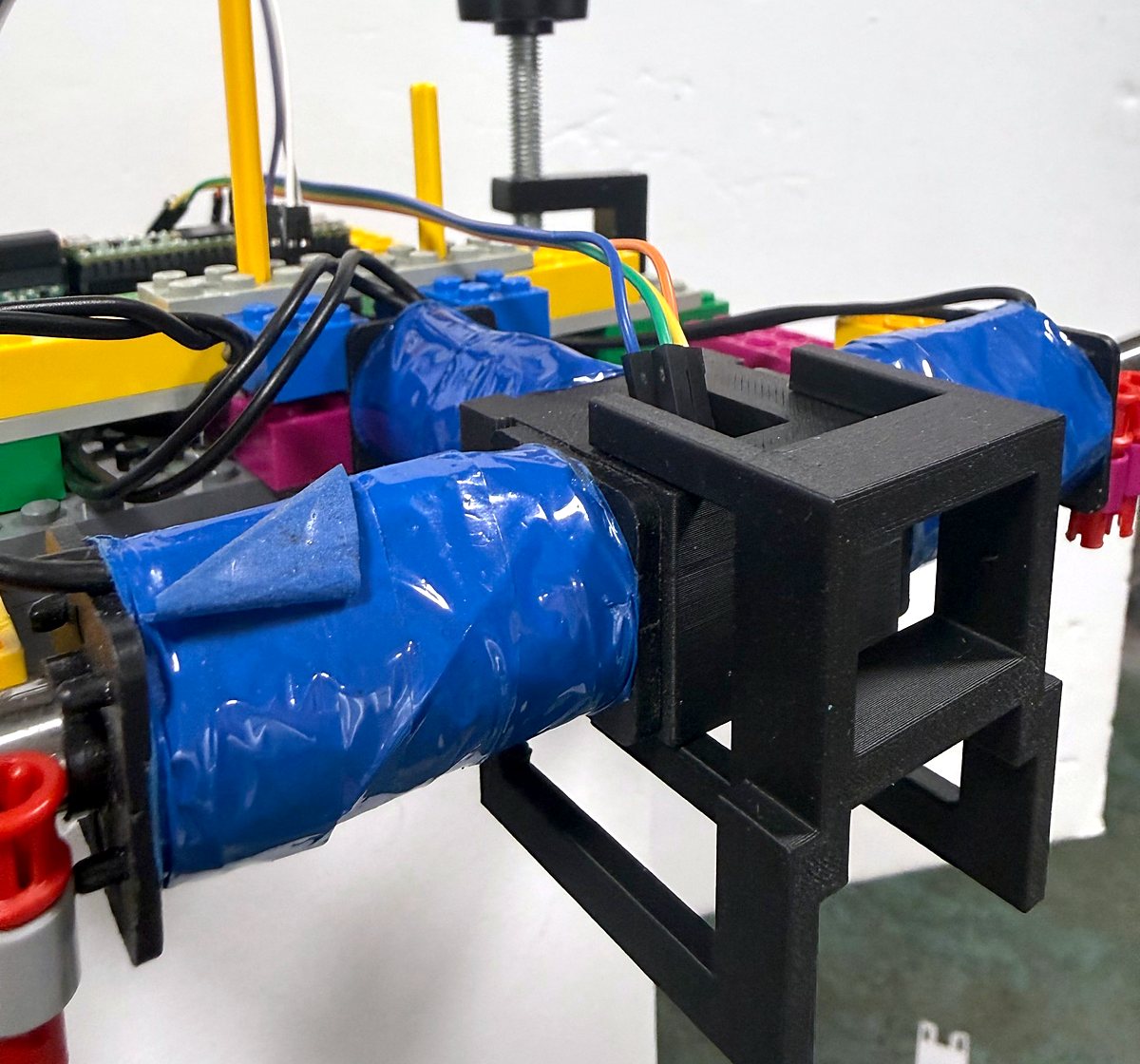
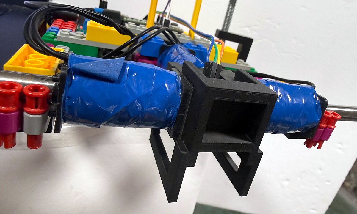
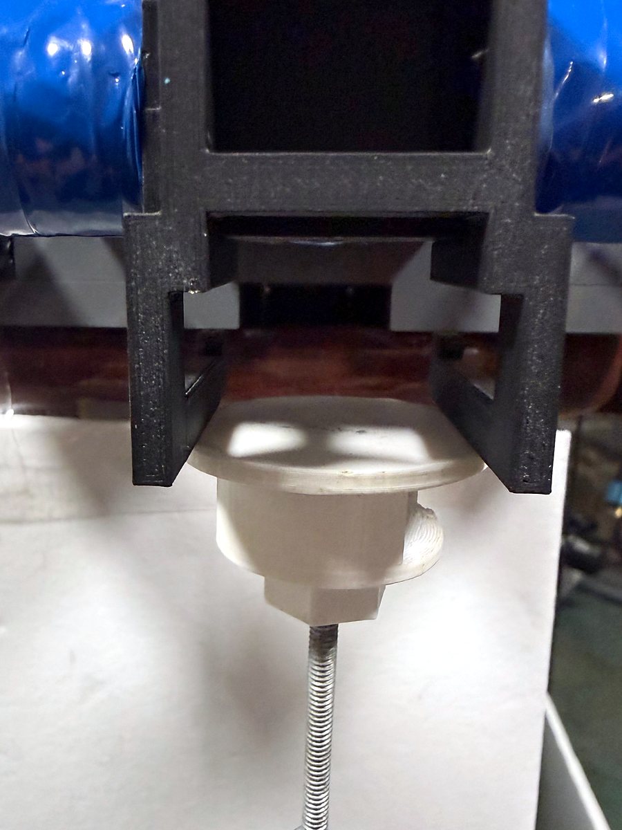
- −10 mm: clip the calibration attachment onto the bracket (photos below), and let the electromagnet pull the umbrella up against the bottom of the attachment. Note the reading.
Your readings should fall in these ranges:
| Position | Sensor reading |
|---|---|
| +15 mm (against the bracket) | 0.80 to 0.90 |
| −10 mm (against the bottom of the attachment) | 0.06 to 0.16 |
If either reading is out of range, check the optical-sensor wiring, especially the 3V connection and the 10 kΩ resistor from IN5 to Gnd, then ask a staff member.