Propeller Arm Assembly Guide
Please Log In for full access to the web site.
Note that this link will take you to an external site (https://shimmer.mit.edu) to authenticate, and then you will be redirected back to this page.
Download the sketch for the propeller arm, 6310_PROP_22_23.zip.
Please follow the instructions below to assemble the arm. You will be using the propeller arm for the several labs, so please assemble with care.
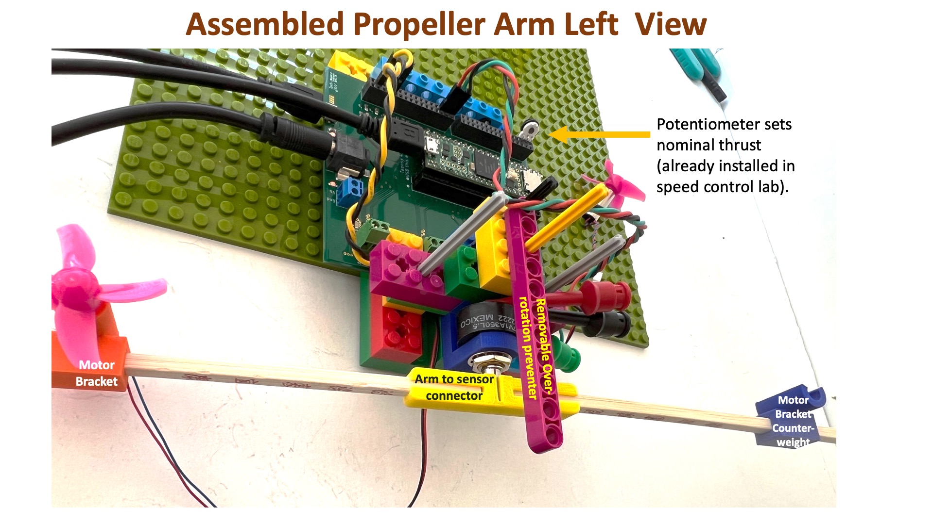
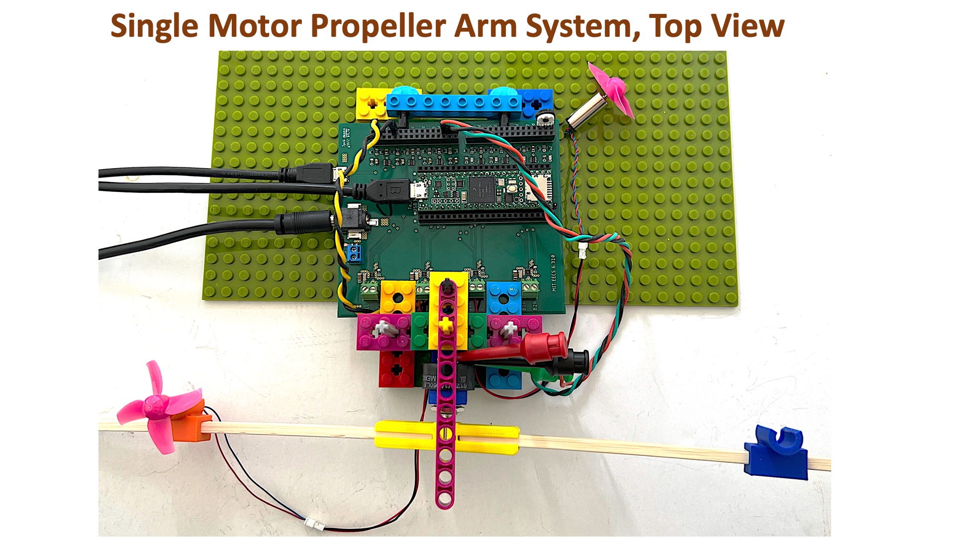
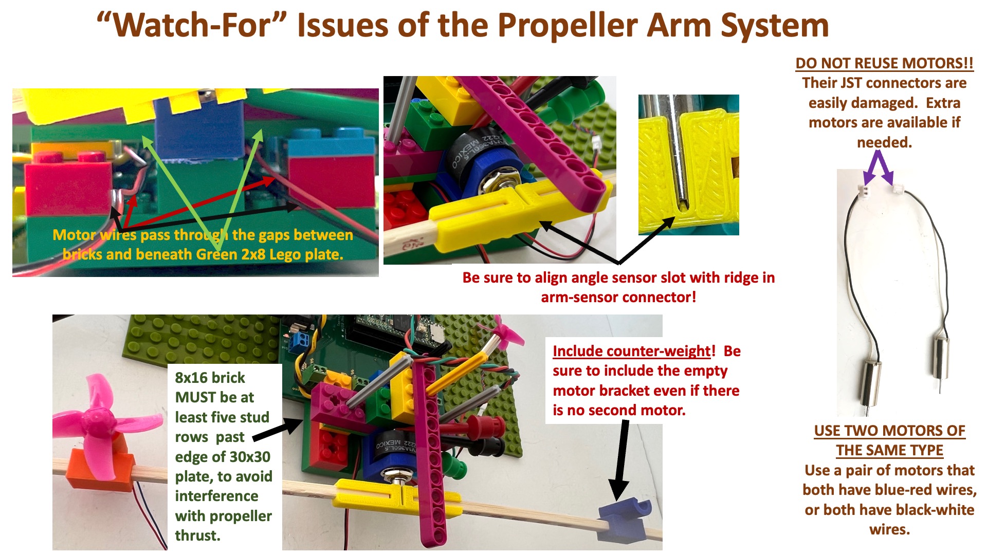
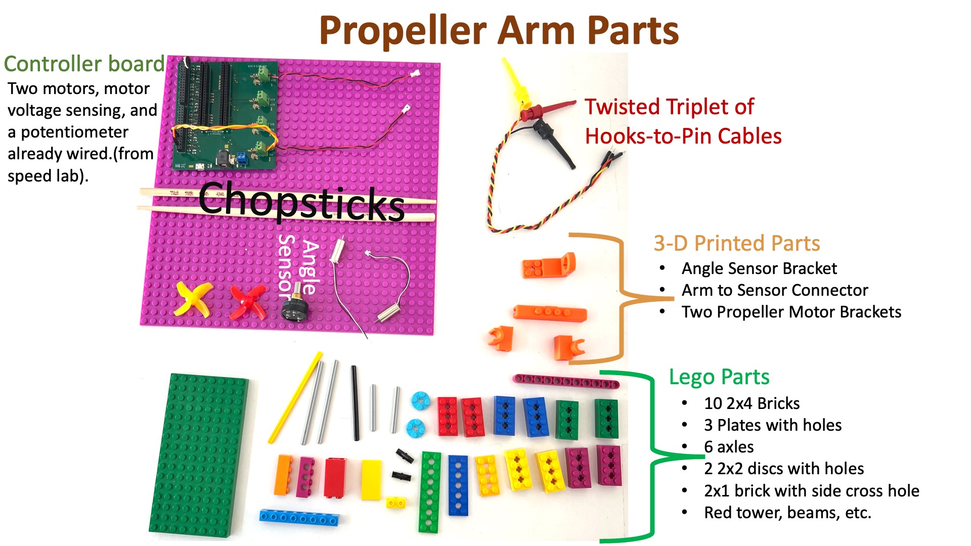
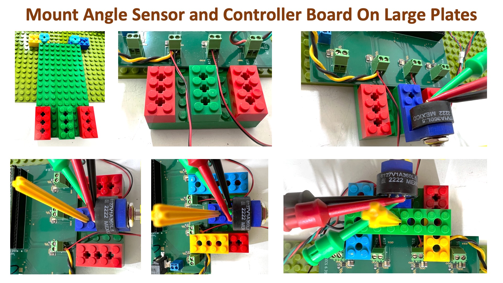
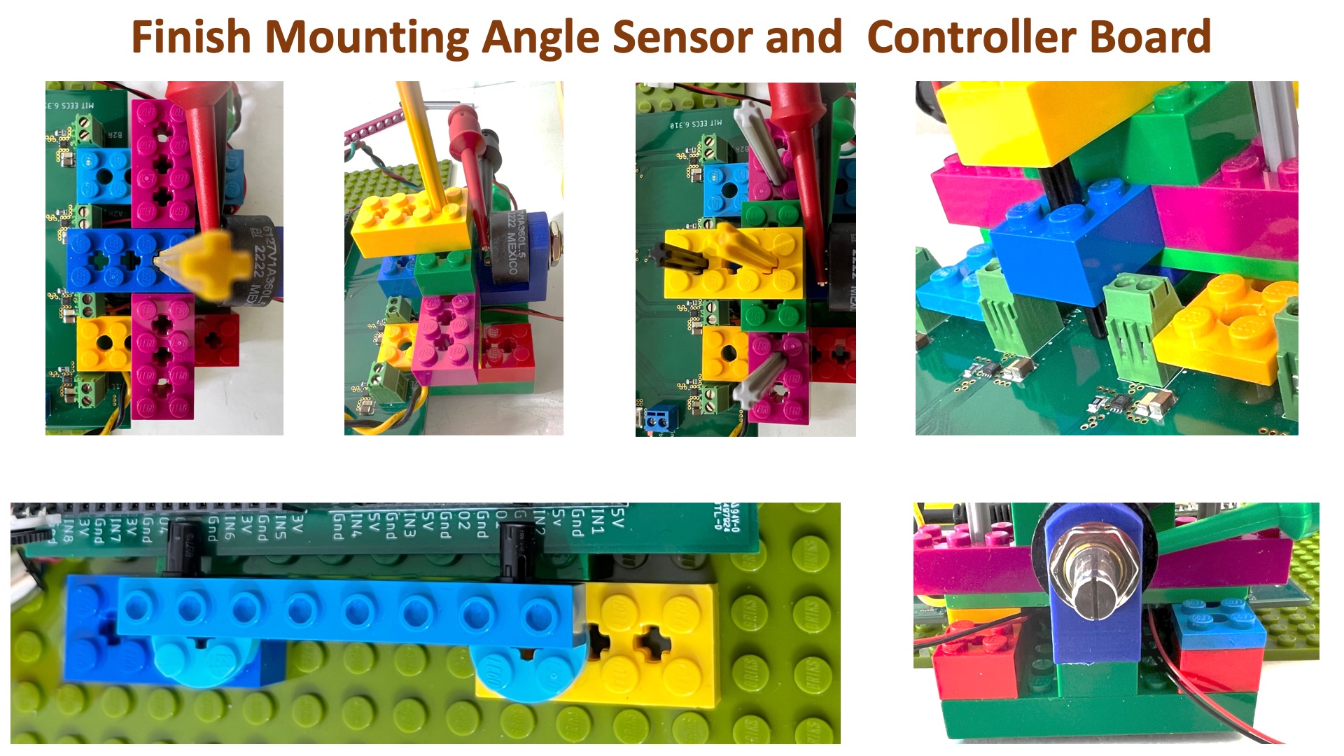
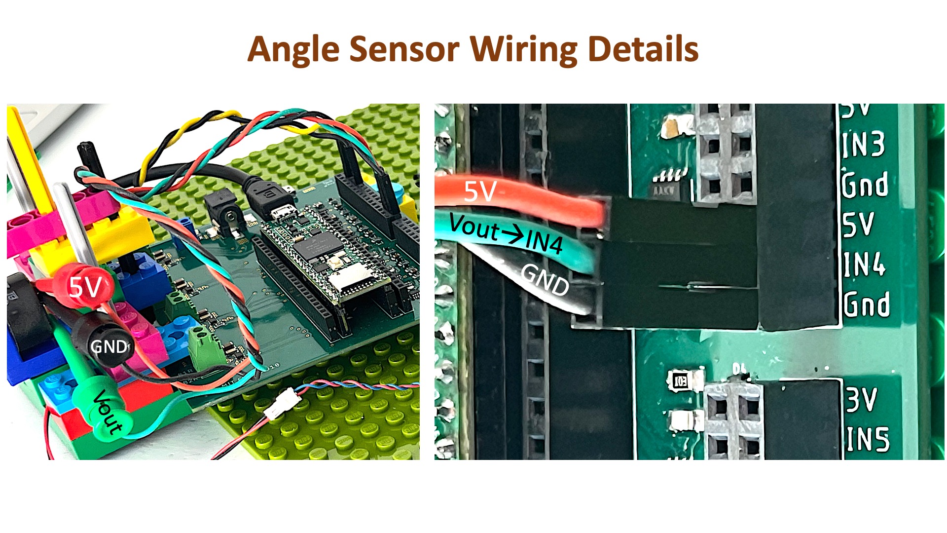
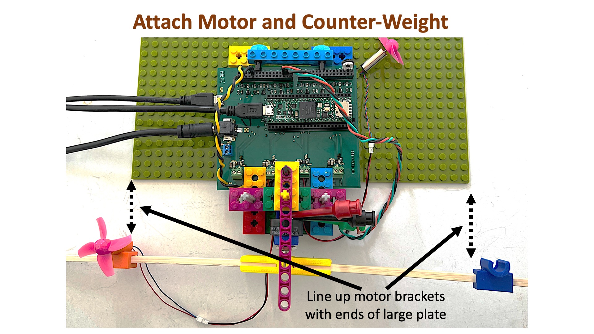
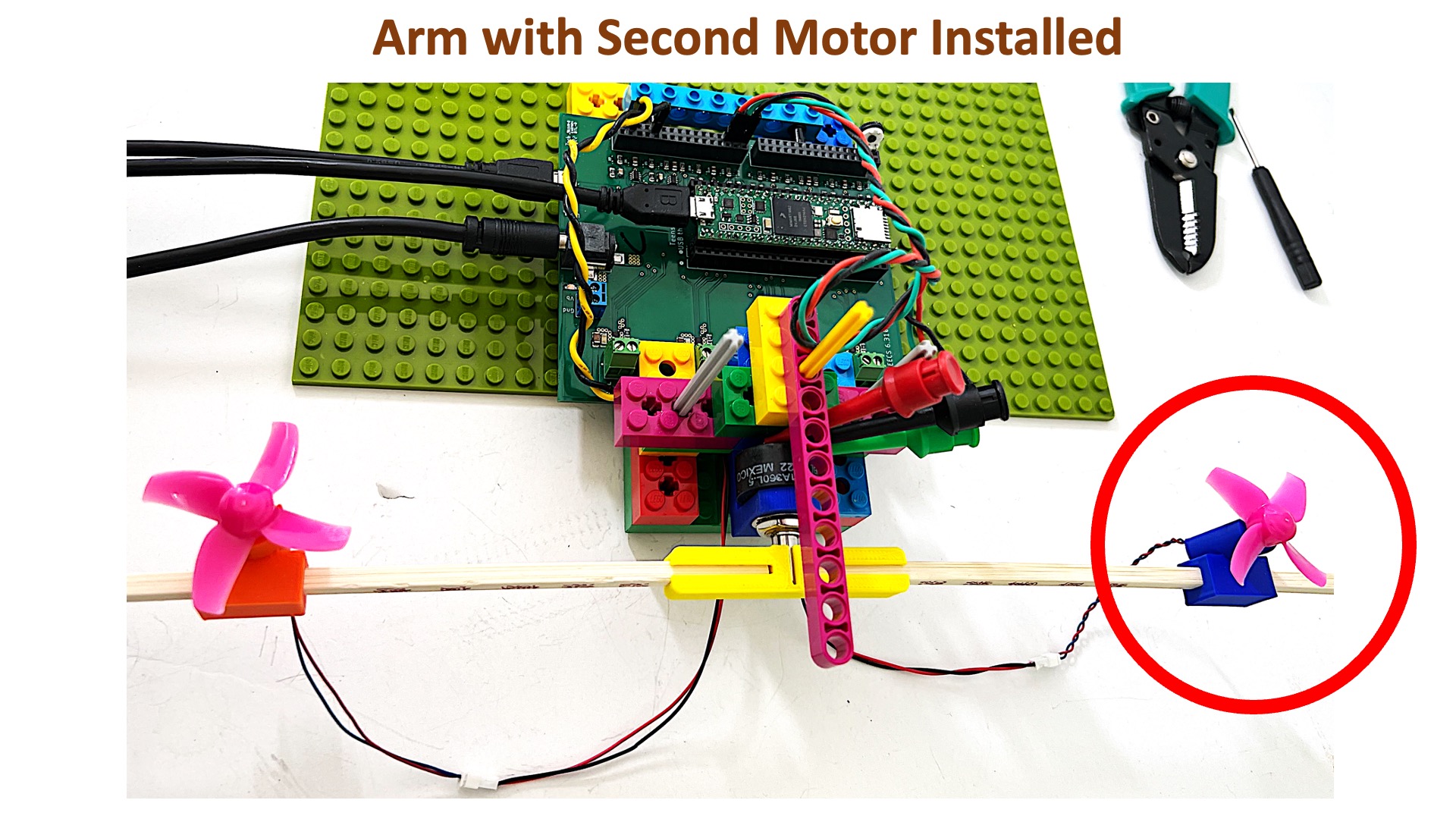
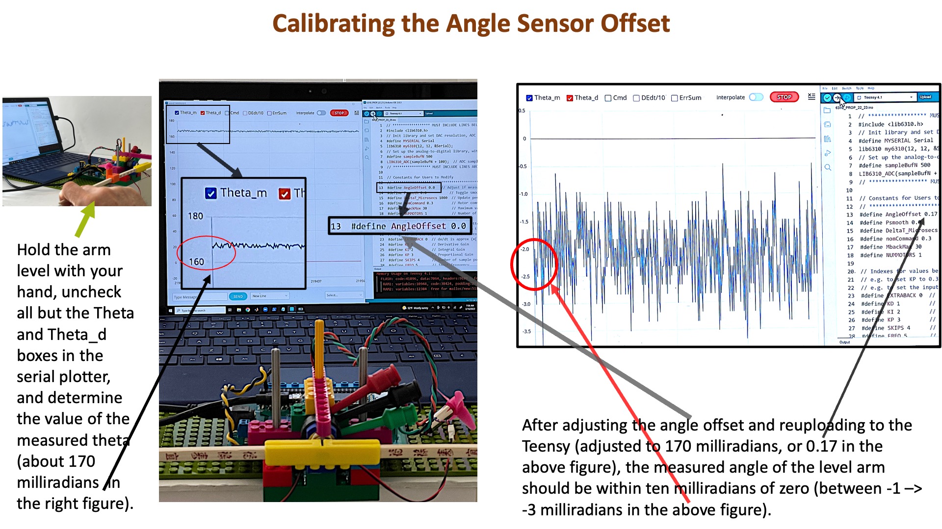
Connect your laptop to the Teensy 4.1 and just the USB 5V supply (and NOT the large 5V 8amp supply) to the controller board. Download and unzip the Teensy propeller arm control sketch (link at top of page), upload the sketch to the Teensy 4.1, and then start the serial plotter.
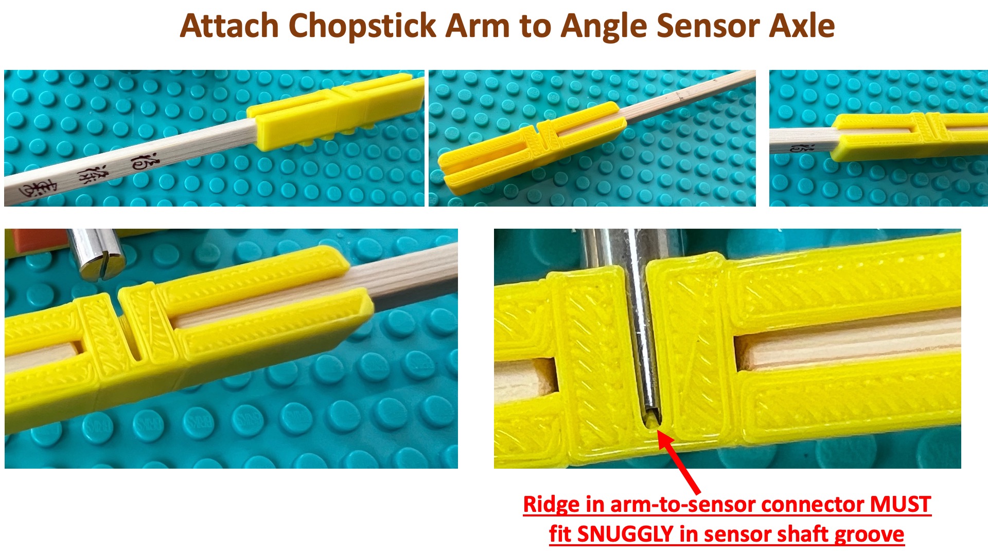
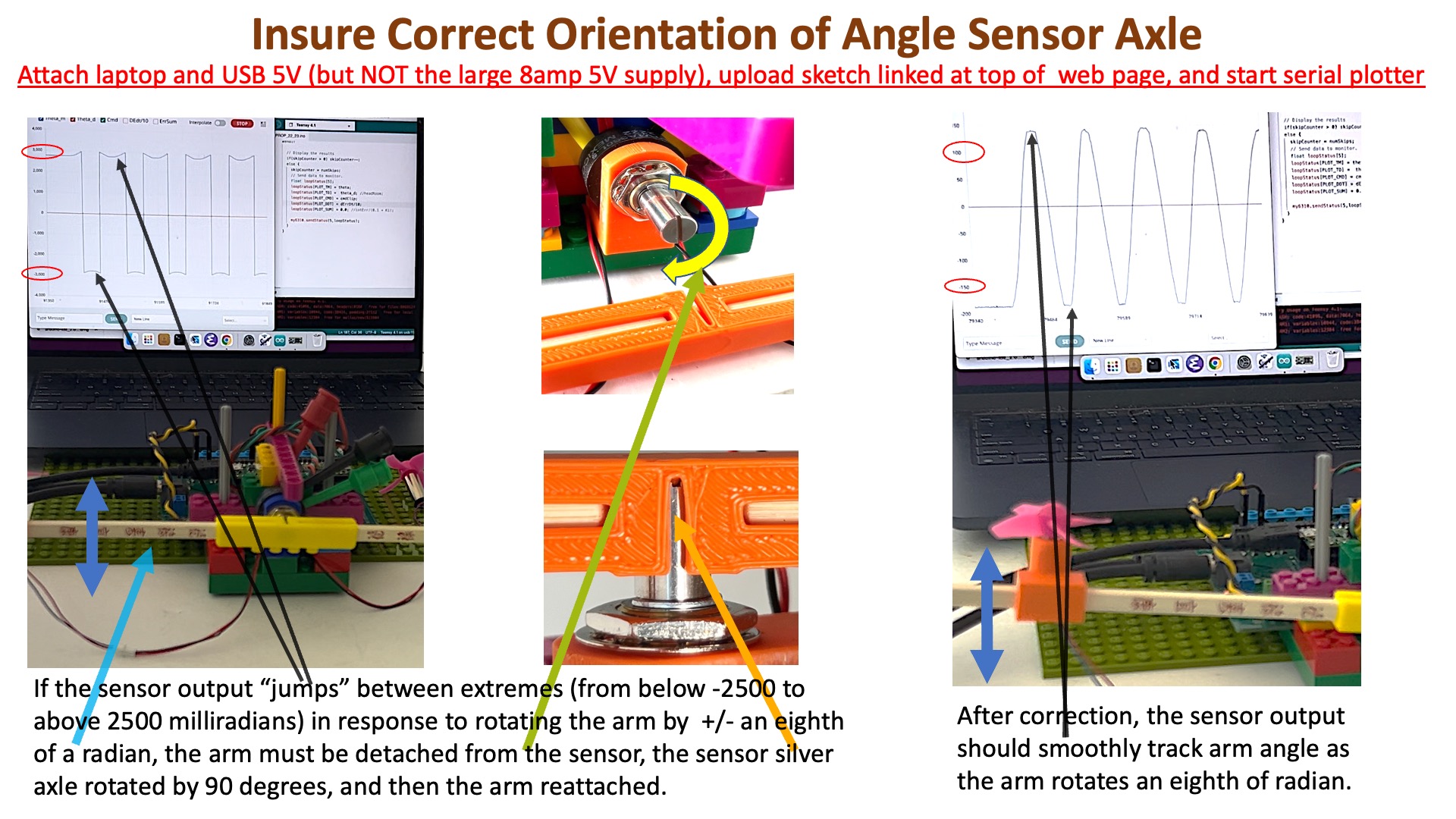
The angle sensor axle will correctly fit into the arm connector ONLY if the slit in the axle is aligned with the small outcropping in the connector. Unfortunately, there are two possible slit-connector alignments that fit correctly, and one mis-rotates the sensor axle by a half rotation. Watch the two videos and exam the figure below to learn how to ensure your angle sensor axle is correctly oriented in the connector.
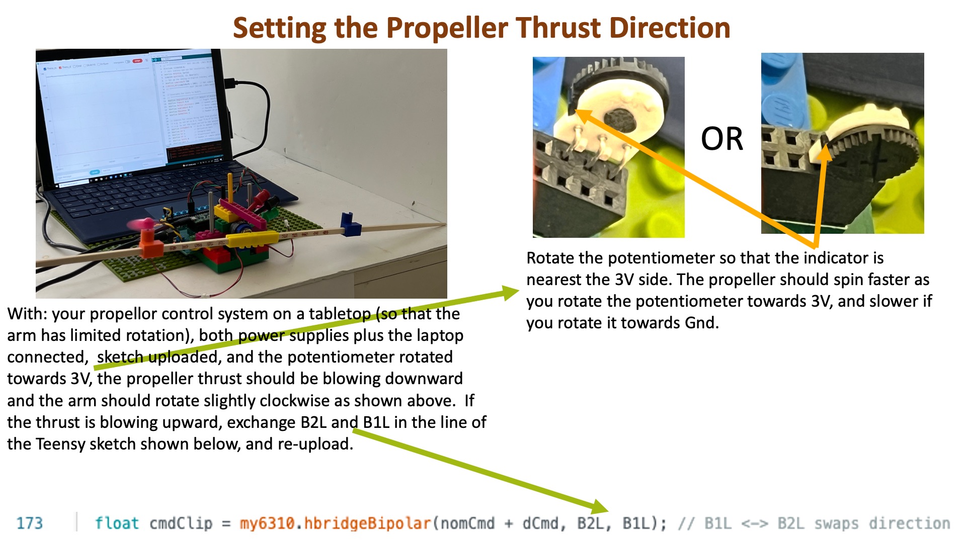
Place your propellor control system on a tabletop (so that the arm has limited rotation), make sure your laptop is connected to the Teensy 4.1, and the USB 5V supply connected to the controller board. Then upload the sketch to the Teensy 4.1 and ONLY THEN connect the 5V 8amp supply to the controller board. Adjust the motor command in the Teensy sketch, as show in the figure below, so that the arm rotates clockwise.
Once you have verified that the arm angle sensor axle is oriented correctly, the sensor is calibrated, and the propeller thrust is in the correct direction, you are ready to start the LAB!
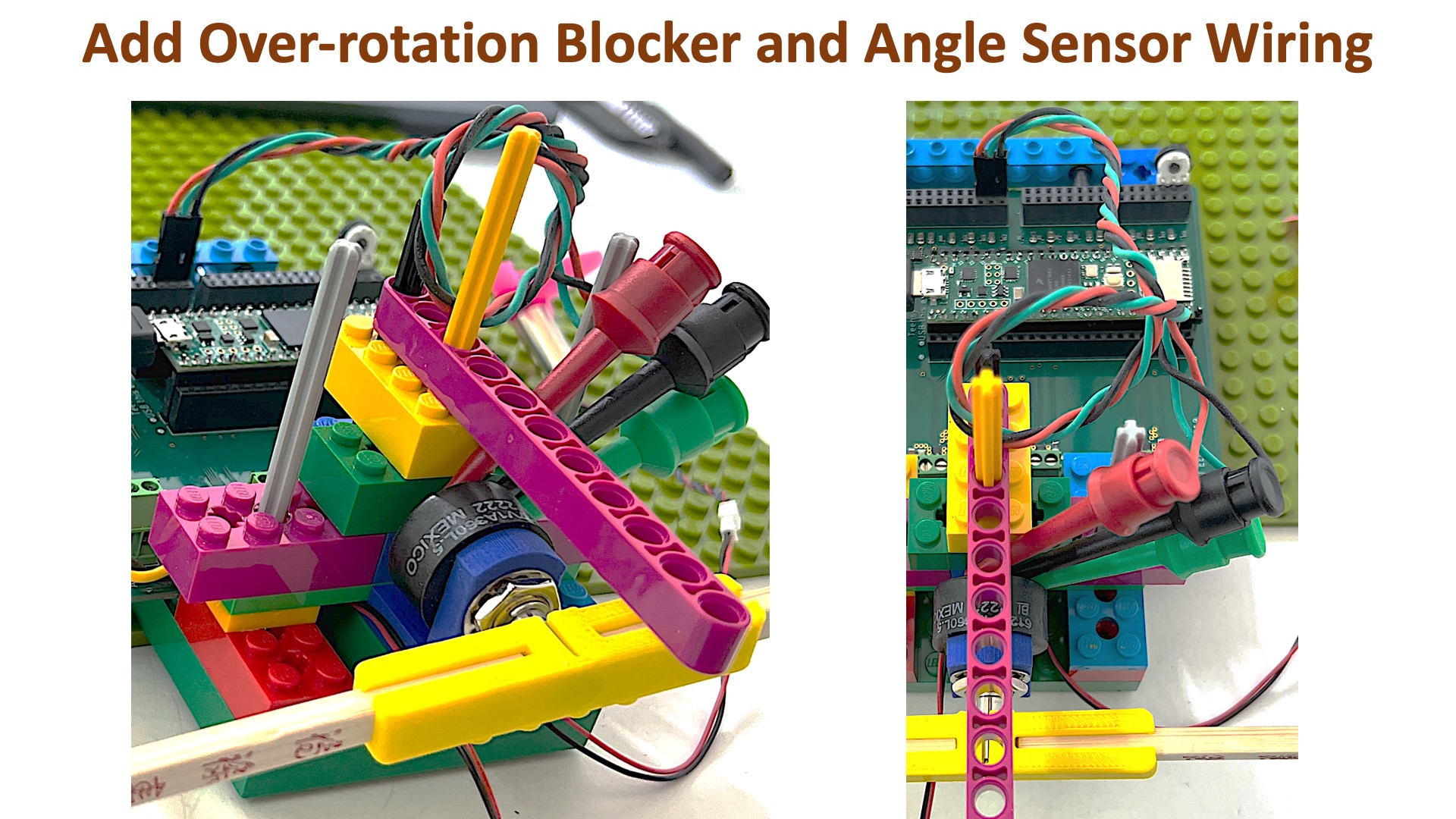
Place your propellor control system so that the arm hangs off the edge of a desk or table (and can rotate freely, though be sure you've attached the purple over-rotation preventer is attached). prevlimit (so that the arm has limited rotation), make sure your laptop is connected to the Teensy 4.1, and the USB 5V supply connected to the controller board. Then upload the sketch to the Teensy 4.1 and ONLY THEN connect the 5V 8amp supply to the controller board. Adjust the motor command in the Teensy sketch, as show in the figure below, so that the arm rotates clockwise.