Propeller Arm Assembly Guide
Please Log In for full access to the web site.
Note that this link will take you to an external site (https://shimmer.mit.edu) to authenticate, and then you will be redirected back to this page.
The Propeller Arm Sketch
Download the sketch for the propeller arm, 6310_PROP_24.zip.
Propeller Arm (Using Last Term's Design!) in Action
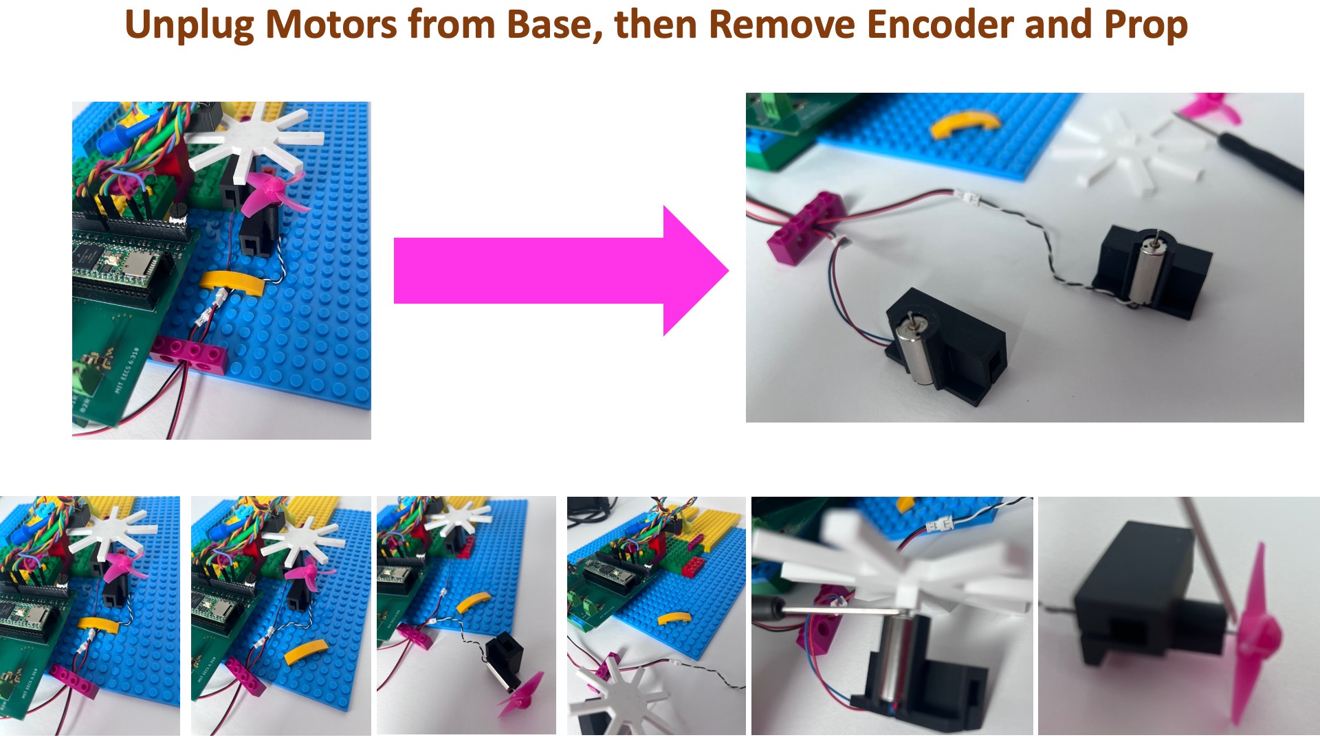
Propeller Arm Assembly
Please follow the instructions below to assemble the arm. You will be using the propeller arm for the several labs, so please assemble with care.
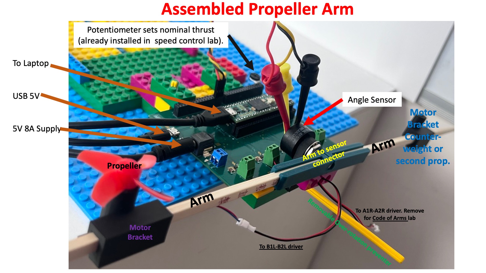
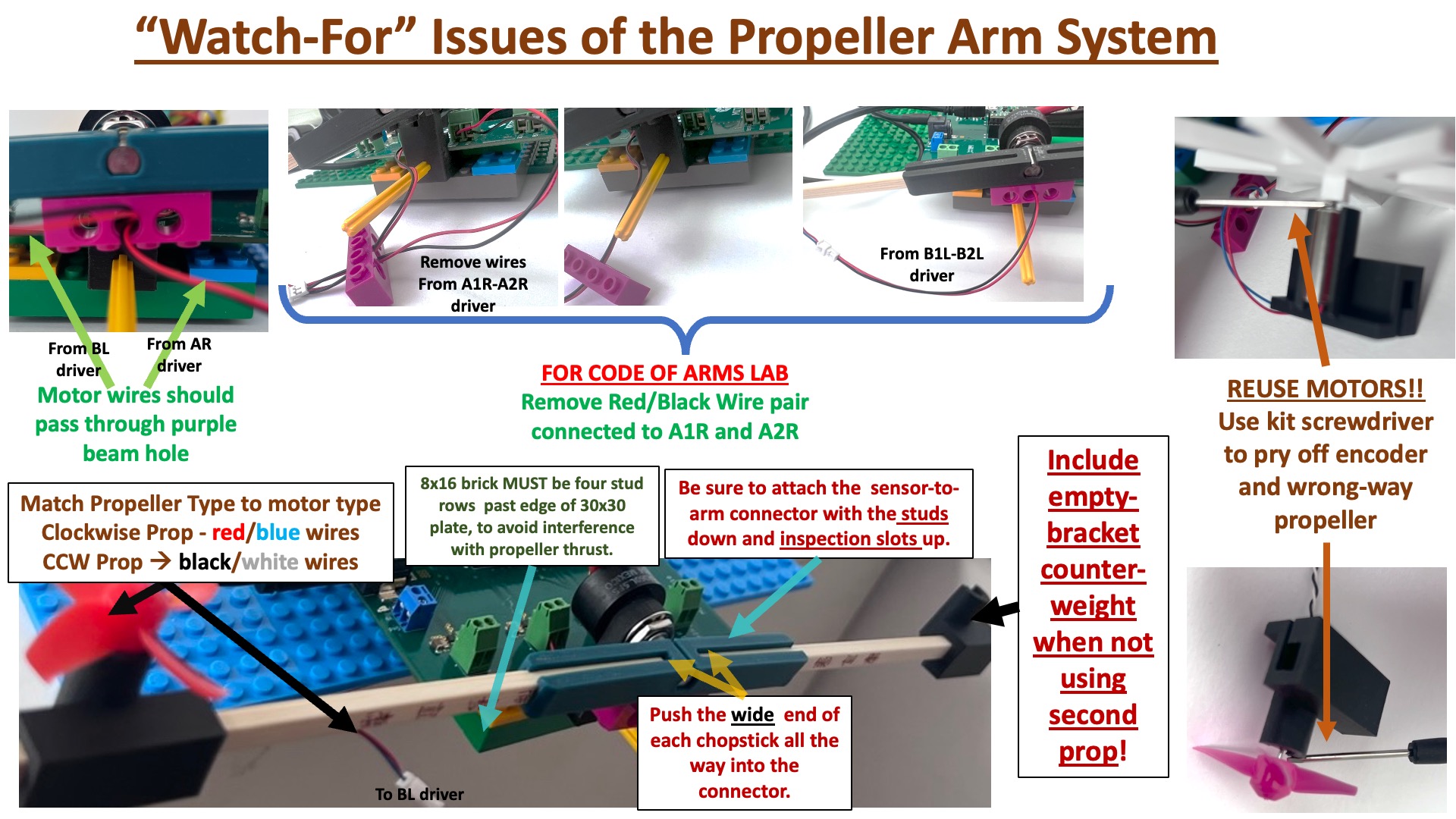
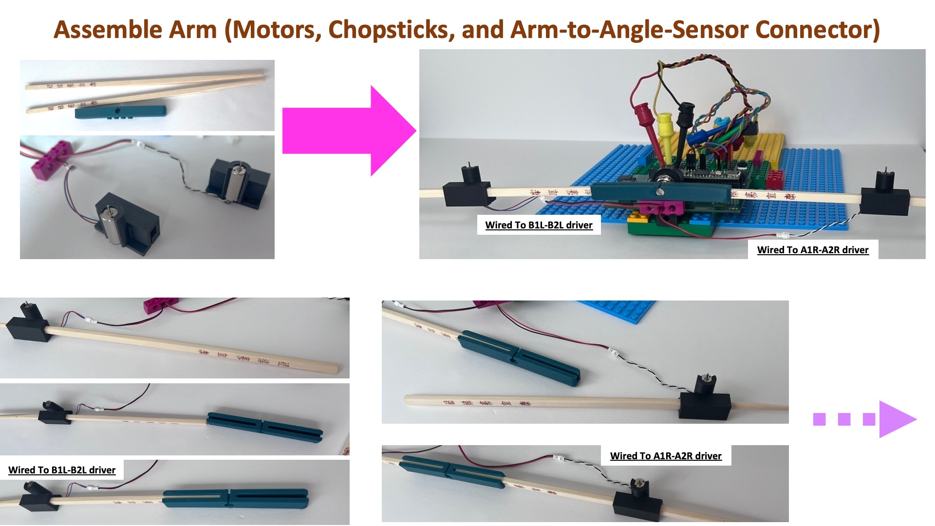
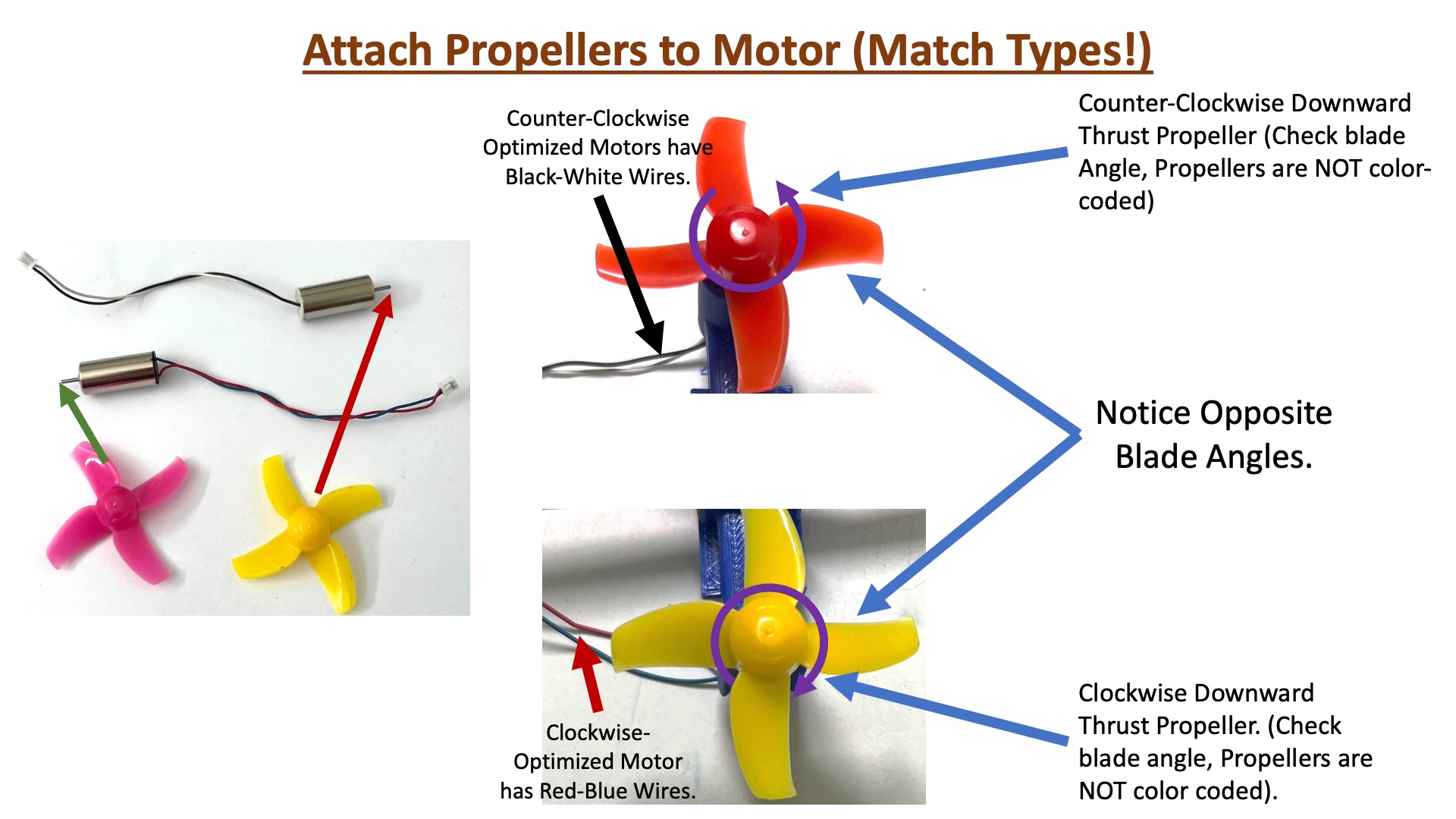
The left motor should be wired to B1L (red wire) and B2L (black wire).
Calibrating the Propeller Arm
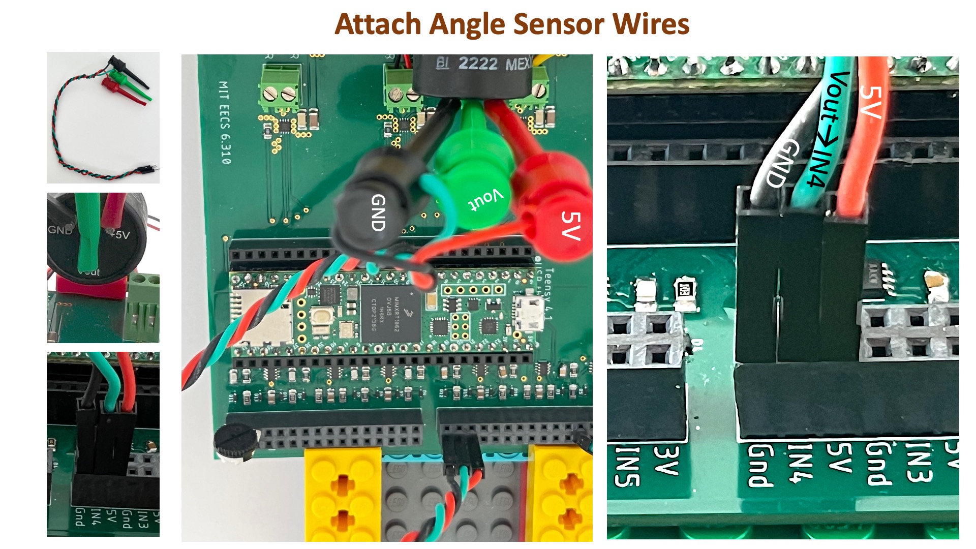
The Angle Sensor
Connect your laptop to the Teensy 4.1 and just the USB 5V supply (and NOT the large 5V 8amp supply) to the controller board. Download and unzip the Teensy propeller arm control sketch (link at top of page), upload the sketch to the Teensy 4.1, and then start the serial plotter.
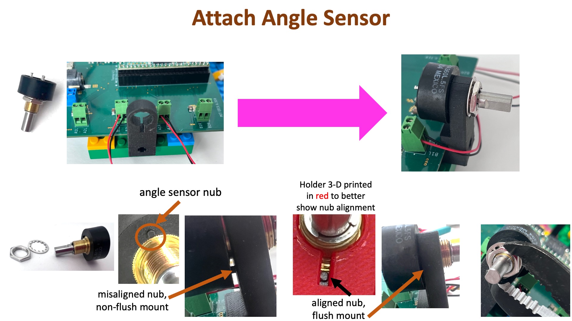
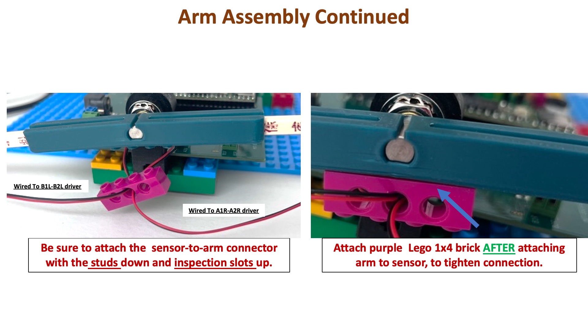
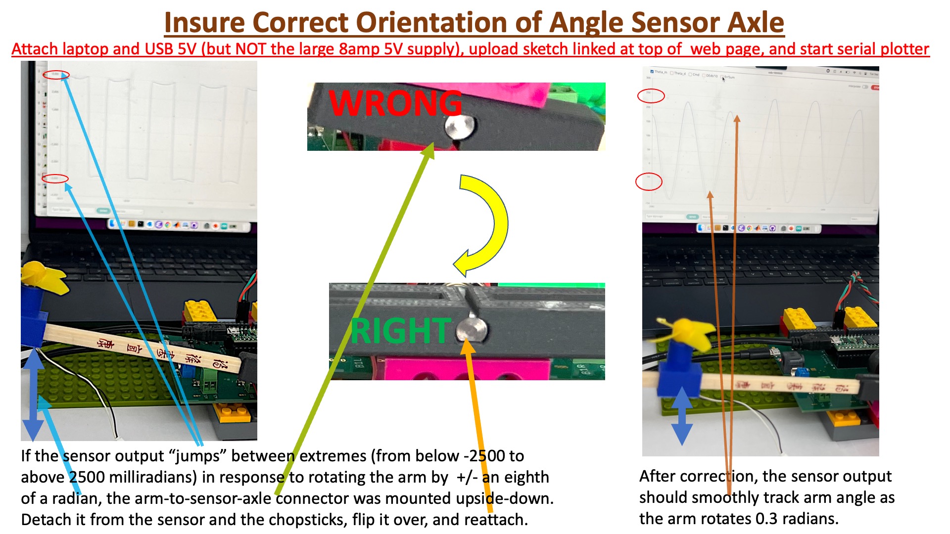
Sensor Axle orientation
The angle sensor axle will correctly fit into the arm connector ONLY if the slit in the axle is aligned with the small outcropping in the connector. Unfortunately, there are two possible slit-connector alignments that fit correctly, and one mis-rotates the sensor axle by a half rotation. The procedure for fixing the sensor is detailed in the image below.
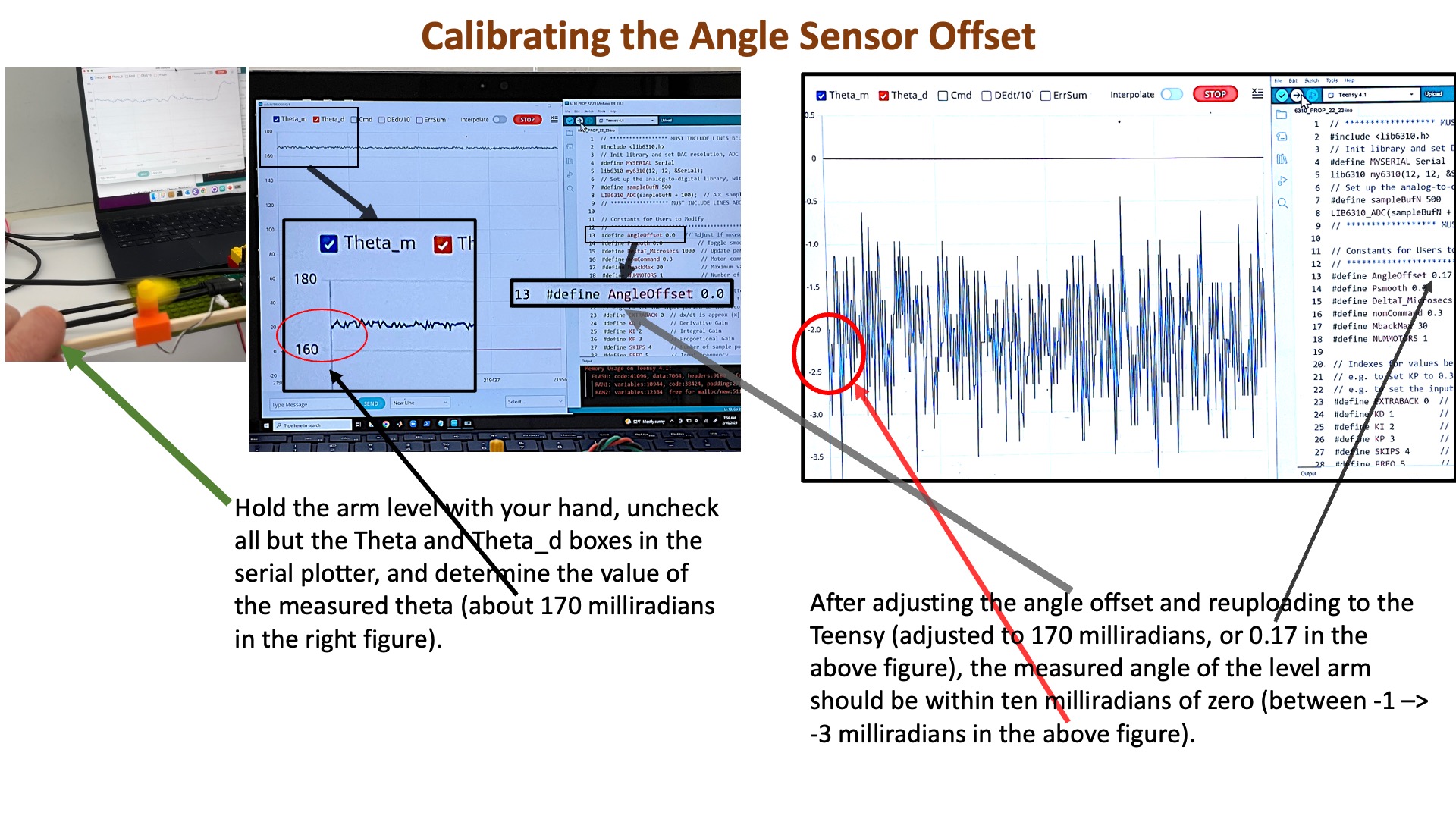
Angle Sensor Calibration
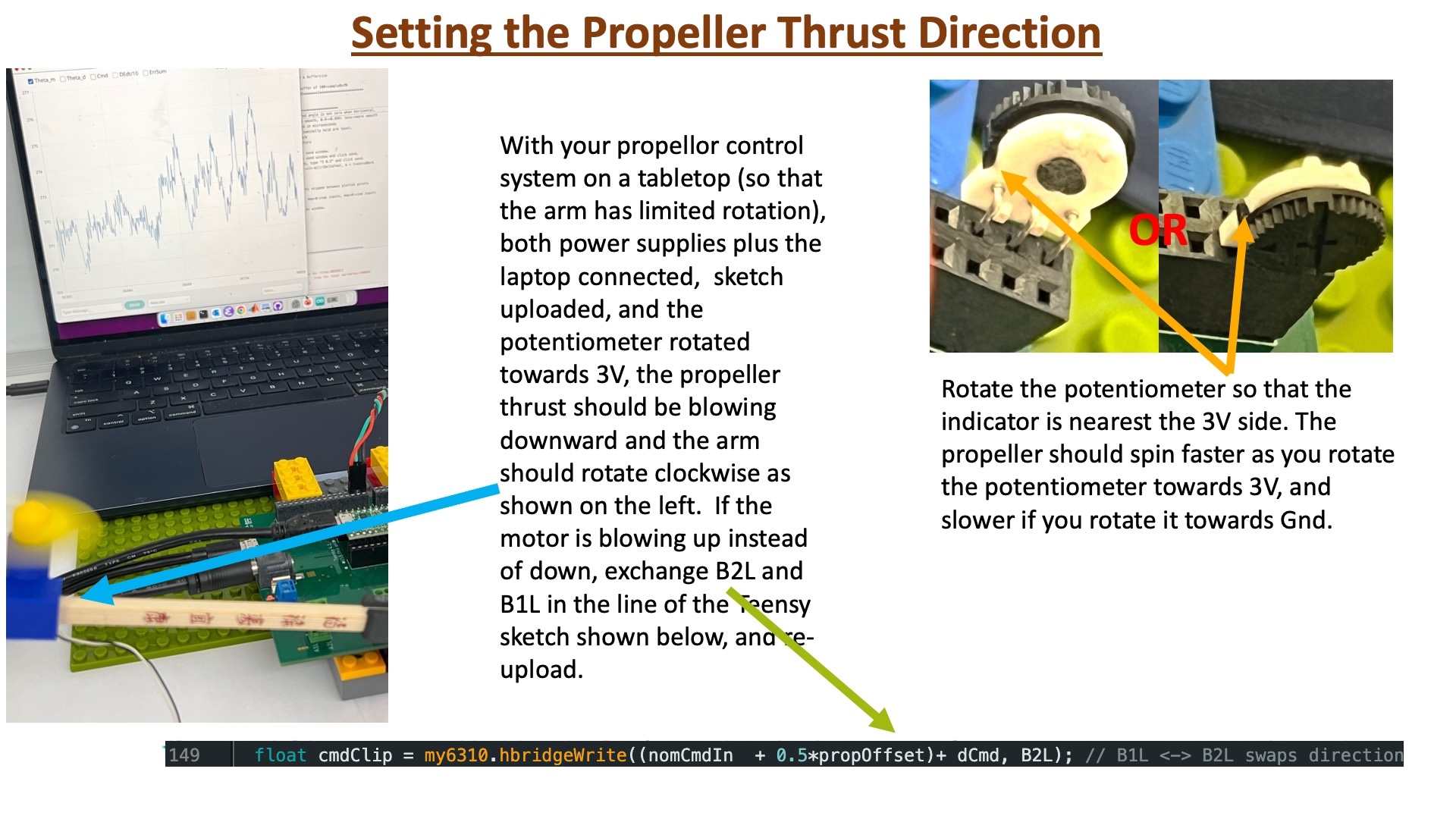
Setting Propeller Thrust Direction
Place your propeller control system on a tabletop (so that the arm has limited rotation), make sure your laptop is connected to the Teensy 4.1, and the USB 5V supply connected to the controller board. Then upload the sketch to the Teensy 4.1 and ONLY THEN connect the 5V 8amp supply to the controller board. Adjust the motor command in the Teensy sketch, as show in the figure below, so that the arm rotates clockwise.
Leveling the Single Propeller Arm
We define the arm as having zero rotation, \theta_a = 0, when the arm is level, or horizontal. But holding the single-propeller arm horizontal requires that the propeller produce enough thrust to balance gravity. We refer to the motor command associated with this gravity-balancing thrust as the nominal command, and in this last section, we will determine that command experimentally.
Force of Arms
In the top half of the figure below, we show an image of propeller arm in the level (horizontal) position, and make note of the torque-producing gravity- and thrust-generated forces. In the bottom half of the figure, we note the same forces on a "cartoon" of the arm, a simplified picture that appears frequently in our lab descriptions because the cartoon makes the salient features more visible.
As you can see from either picture, to hold the arm level requires a nominal motor command for which the associated thrust-generated arm torque exactly balances the torque due to gravity forces.
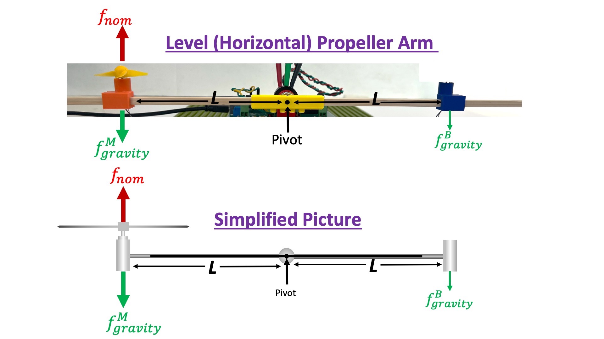
As the above figure shows, there are three torques acting on the rigid arm due to three forces: propeller thrust, motor gravity, and empty bracket (counter-weight) gravity. Since all three forces act at a distance L from the pivot, as can be seen in the above figure, the propeller thrust must exactly balance the motor gravity force minus the bracket gravity force. Using the notation in the above figure,
Procedure
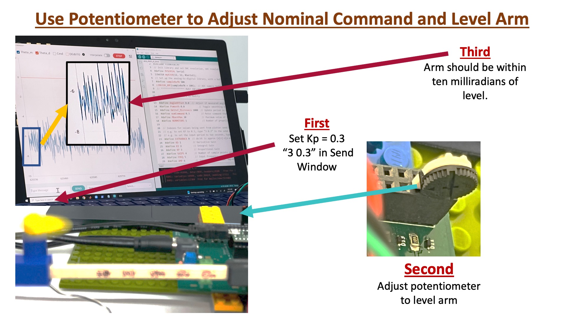
Place your propeller control system so that the arm hangs off the edge of a desk or table, and can rotate freely (though be sure you've attached the purple over-rotation preventer, see the image below). Make sure your laptop is connected to the Teensy 4.1, and the USB 5V supply is connected to the controller board. Then upload the sketch to the Teensy 4.1, start the serial plotter, unclick all the plot check boxes except for the theta and theta_d plots, AND use the send window to set the proportional feedback gain, K_p, to 0.3 (by typing 3 0.3 in the send window). Finally, while holding the propeller arm level with your hand, connect the 5V 8amp supply and then adjust the nominal command potentiometer until you feel the arm hold itself level.
If the arm will not hold a level position (as in the figure below), try rotating the arm clockwise and then counter-clockwise from level. If the arm is working correctly, the propeller will slow down when rotated clockwise from level, and speed up when rotated counter clockwise from level (because the control system uses NEGATIVE feedback). If the behavior of your arm is different, ask for help.