Op-amp Feedback
Please Log In for full access to the web site.
Note that this link will take you to an external site (https://shimmer.mit.edu) to authenticate, and then you will be redirected back to this page.
Single Pole Op-Amp
Consider a nearly ideal op-amp whose transfer function from input difference (V_+ - V_-) to output voltage V_o is given by
If we use what is usually referred to as non-inverting configuration, using resistors R_1 and R_2 to create the feedback network. This op-amp may be modeled using a feedback block diagram, with a 'forward-path' given by H_{OPAMP}(s) and a 'feedback path' scaled by a factor f.
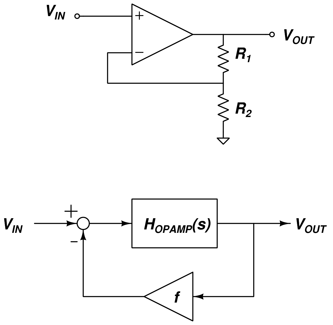
This is not our usual tracking configuration, because the output is scaled by f before comparing to the input, but this form is more natural when describing operational amplifier circuits. To analyze this case, we know that based on how the circuit elements are connected,
The operational amplifier's output voltage, V_{out} is determined by the product of its transfer function and the differential input voltage,
Combining,

What values of the feedback factor f are realizable using the resistor network? Open circuit (R=\infty) and short-circuit (R=0) resistor values are allowed.
Recall that the step response for a first-order differential equation system
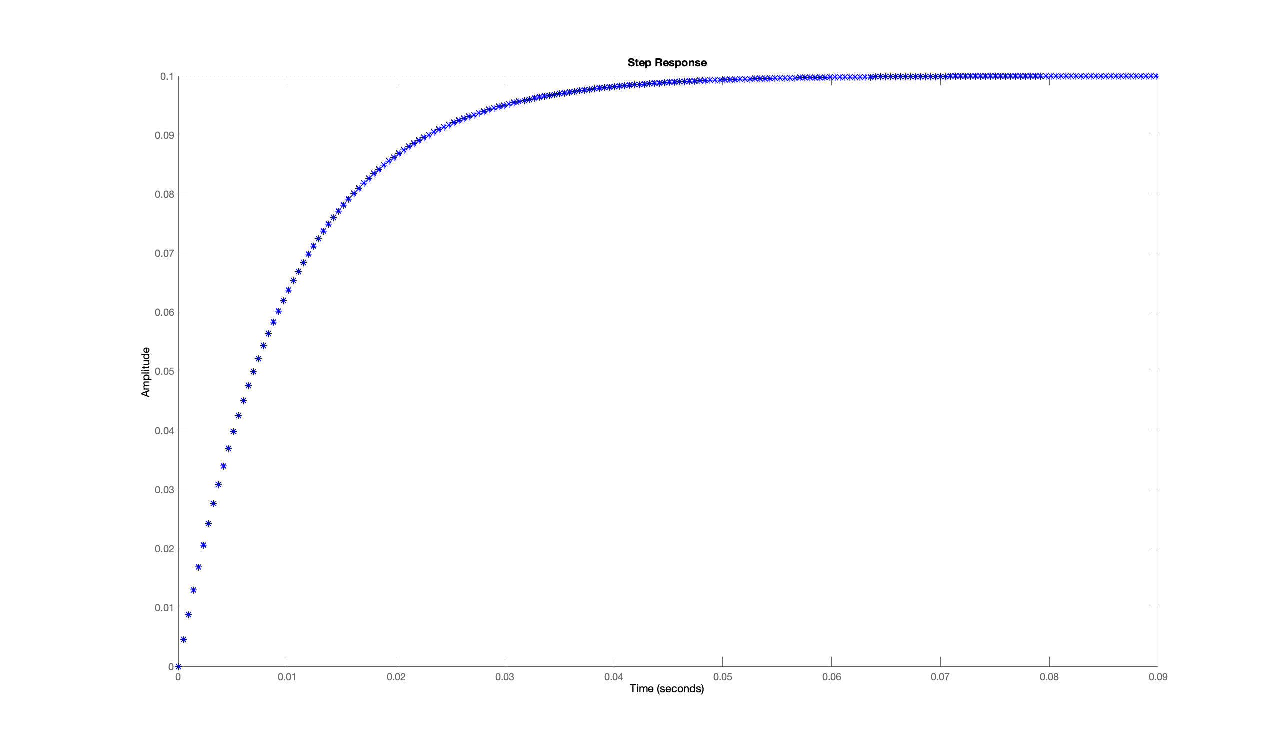
For steady-state gains from one to one thousand (corresponding to \frac{1}{1000} \le f \le 1) give an approximate expression for the relationship between gain and the time for the step response to achieve two-thirds of steady-state.
Suppose R_1 = 10^6 ohms (which we often refer to as a 1M\Omega or one megohm) and R_2 = 100 ohms, to within 0.1 percent, what is the steady-state gain?
In lab, you will be building an op-amp PD controller, with the following topology.
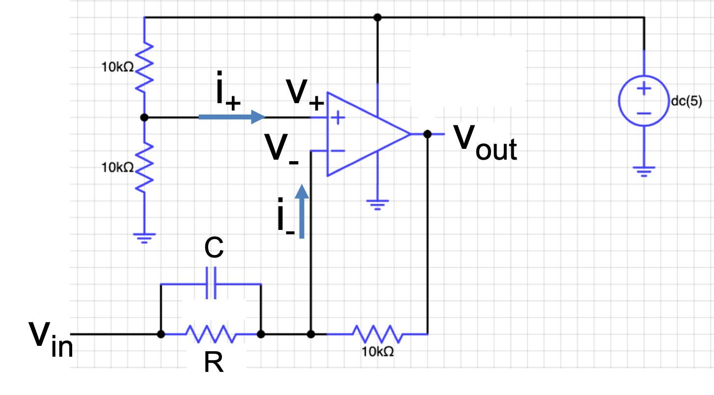
Please analyze the op-amp making the "design" assumptions. That is, v_{out}(t) changes so as to make v_+(t) \approx v_-(t), i_+(t) =0, and i_-(t) = 0.
If nothing is connected the v_{in} terminal, what are the steady-state values of v_+ and v_{out}?
If v_{in} = 2.4, as a function of R, what are the steady-state values of v_+ and v_{out}. Be sure to use 10000 to denote the 10k \Omega resistor value.
Assuming R = \infty and op-amp is ideal, 2.5 - v_{out} is related to v_{in} - 2.5 by a transfer function \mathcal{G}(s) = K_d s . In terms of C, what is K_d?
Assuming R \ne 0 and op-amp is ideal, 2.5 - v_{out} is related to v_{in} - 2.5 by a transfer function \mathcal{G}(s) = K_p + K_d s . In terms of R, C, and s, what is \mathcal{G}(s)?