A Tale of Two Topologies
Please Log In for full access to the web site.
Note that this link will take you to an external site (https://shimmer.mit.edu) to authenticate, and then you will be redirected back to this page.
In the previous section you worked on questions dealing with compensators in a mathematical domain using Matlab tools like bode and margin to help reason about systems based on their transfer functions. These exercises shift the focus to exploring different circuit implementations (also known as topologies) of those compensators. However, still feel free to use matlab or other computational tools to aid in answering the questions.
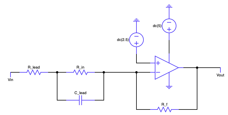

For both topologies, if we lump together R_{lead}, R_{in}, and C_{lead} into a single element with impedance Z_{eq}, what is the transfer function from V_{in} to V_{out} (or equivalently 2.5 - V_{in} and V_{out} - 2.5) in terms of R_f and Z_{eq}? Use Z_eq for Z_{eq} and R_f for R_f.

One useful way to write the system transfer function from V_{in} to V_{out} is in the form
since it becomes much more obvious what the value of the pole and the zero are when it is written like this.
What are the values of \frac{A}{B}, C, and D for the entire system transfer function in terms of R_{lead}, R_{in}, C_{lead}, R_{f}, and s. Use R_lead for R_{lead}, C_lead for C_{lead}, R_in for R_{in}, R_f for R_{f}.
Often times we are interested in what happens at extremely high frequencies and extremely low frequencies (DC).
What is transfer function of whole network including R_f as the frequency approaches zero? This is known as the DC gain of the system. Assume R_{lead} = 100 Ohms, R_{in} = 10000 Ohms, C_{lead} = 10 uF, and R_{f} = 220000 Ohms.
What is transfer function of whole network including R_f as the frequency approaches infinity? Assume R_{lead} = 100 Ohms, R_{in} = 10000 Ohms, C_{lead} = 10 uF, and R_{f} = 220000 Ohms.
What values of R_{lead}, R_{in}, and C_{lead} would you use to create the following transfer function
Assume R_f = 220000 Ohms.
The difference between the two topologies may seem small at first, but lets see what happens as we change the value of R_{lead} relative to R_{in}. Assume R_{in} = 10000 Ohms, C_{lead} = 10 uF, and R_{f} = 220000 Ohms.
For R_{lead} = 100 Ohms
For R_{lead} = 1000 Ohms
For R_{lead} = 10000 Ohms